bnp-b2365(eng)b.pdf - 第286页
5. Spindle Adjustment 5 - 41 [3] Adjustment of positio n loop gain deceler ation rate Adjust the orientation time and vibration. Refe r to the following table and adjust the parameters according to the apparent state. Wh…
5. Spindle Adjustment
5 - 40
(2) Adjusting the orientation deceleratio n control
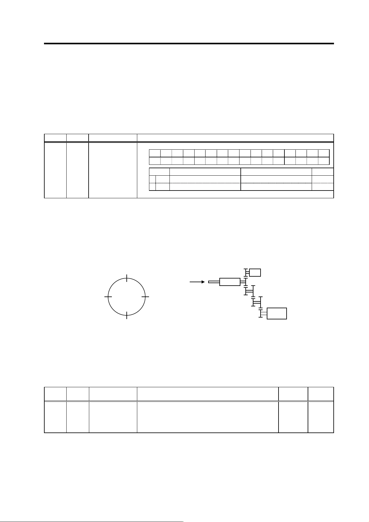
[1] Polarity setting of sensor
Input the orientation command (ORC) when the machine is in the normal state. Confirm that the
operation stops at one point and the orientation complete signal (ORCF) turns ON even when
the operation is unstable. If the excessive error alarm (alarm 52) o ccurs, or if the operation does
not stop and repeats forward/reverse run at a low-speed when using the magnetic sensor
orientation specifications, change the value for SP097/bit5 or bit6. If the excessive error alarm
occurs even after changing this value, carry out step [3].
No. Abbr. Parameter name Details
FEDCBA98765 4 3 2 10
ostp orze ksft gchg ips2 zdir vg8x mdir fdir Oscl pyfx dmin odi2 odi1
bit Meaning when set to 0 Meaning when set to 1 Standard
5 fdir Spindle end detector polarity: + Spindle end detector polarity: – 0
6 mdir Magnetic sensor polarity: + Magnetic sensor polarity: – 0
SP097 SPECO* Orientation
specification
[2] Adjustment of orientat ion stop position
Next, adjust the in-position shift amount for orientation control: SP007 (OPST) so that the axis
stops at the target stop point. If the stop position command data is input from the spindle end
detector, or from an external source during motor PLG orientation, the operation will stop
according to the given data as shown in the drawing below regardless of the detector's
mounting direction. The 0° position sh own below is the position shifted by SP007 (OPST).
Orientation stop position
(Note) The external stop position command data is read in at the rising edge of the orientation start, so
always change the value before inputting the orientation start command. Any changes to the value
will be invalid if made after orientation has started.
No. Abbr. Parameter name Details
Setting
range
Standard
SP007 OPST In-position shift
amount for
orientation
Set the stop position for orientation.
(1) Motor PLG, spindle end detector:
Set the value by dividing 360° by 4096.
(2) Magnetic sensor:
Divide –5° to +5° by 1024 and put 0° for 0.
(1) 0 to 4095
(2) -512 to
512
0
View S
0h
(0°)
400h
(90°)
800h
(180°)
C00h
(270°)
S
p
indle end detecto
r
XS
p
indle
Spindle motor
A
BC
DE
F
S
5. Spindle Adjustment
5 - 41
[3] Adjustment of positio n loop gain deceleration rate
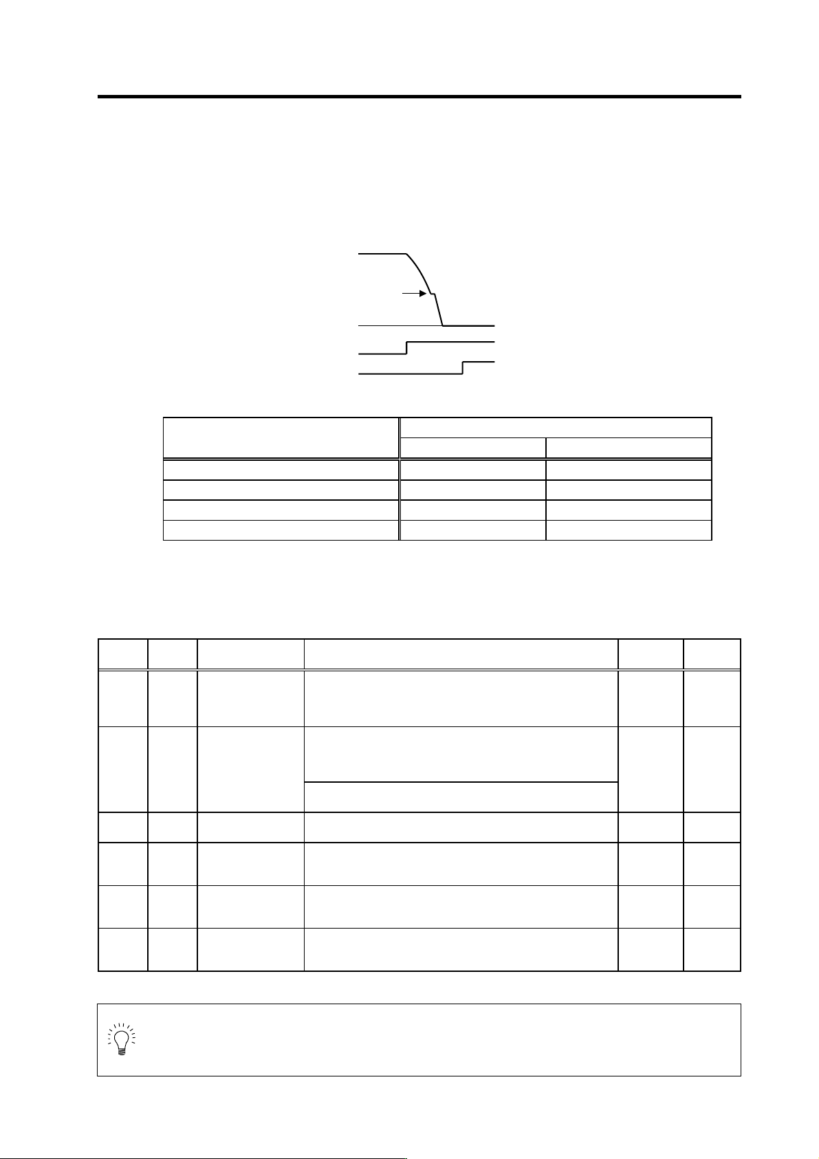
Adjust the orientation time and vibration. Refer to the following table and adjust the parameters
according to the apparent state. When using the motor PLG and magnetic sensor, adjust the
position loop gain with SP001 (PGM). When using the spindle end detector, adjust SP002
(PGE). Adjust SP006 (CSP) after adjusting SP001 and PS002. When performing coil change
over, each coil can be adjusted individually. (Refer to the next page.)
Adjusting the orientation control
Parameter adjustment
State
SP001/SP002 SP006
The operation overshoots when stopping Decrease the setting value Decrease the setting value
The orientation time is long Increase the setting value Increase the setting value
Hunting occurs when stopping Decrease the setting value Do not change the setting value
An excessive error alarm occur s Decrease the setting value Decrease the setting value
To adjust the shortest orientation time for each gear, adjust deceleration rate for each gear by
SP107 (CSP2) to SP109 (CSP4) in the same manner. If an excessive error alarm occurs when
the gear ratio is 1:10 or more, and the state is not improved with the above adjustments, adjust
the speed clamp value (SP 005) as described later.
No. Abbr. Parameter name Details
Setting
range
Standard
SP001 PGM Magnetic sensor,
motor PLG
orientation position
loop gain
The orientation time will be shorter when the value is increased,
and the servo rigidity will increase. On the other hand, the
vibration will increase, and the machine will sway easily.
0 to1000
(0.1rad/s)
100
<For MDS-C1-SP/SPH/SPM>
The orientation time will be shorter when the value is increased,
and the servo rigidity will increase. On the other hand, the
vibration will increase, and the machine will sway easily.
SP002 PGE Encoder orientation
position loop gain
<For MDS-C1-SPX/SPHX>
Set the position loop gain for spindle end PLG orientation.
0 to 1000
(0.1rad/s)
100
SP006 CSP Orientation mode
deceleration rate
As the set value is larger, the orientation time becomes shorter.
However, the machine becomes likely to overshoot.
1 to 1000 20
SP107 CSP2 Deceleration rate 2
in orientation control
mode
Set the deceleration rate in orientation mode corresponding to
the gear 001.
When this parameter is set to "0", same as SP006 (CSP).
0 to 1000 0
SP108 CSP3 Deceleration rate 3
in orientation control
mode
Set the deceleration rate in orientation mode corresponding to
the gear 010.
When this parameter is set to "0", same as SP006 (CSP).
0 to 1000 0
SP109 CSP4 Deceleration rate 4
in orientation control
mode
Set the deceleration rate in orientation mode corresponding to
the gear 011.
When this parameter is set to "0", same as SP006 (CSP).
0 to 1000 0
POINT
On machines with large spi ndle-to-motor gear ratios, it may not be possible to
achieve the desired results by adjusting the SP001, SP002, and SP006 parameters,
due to internal clamping. When clamped, the p arameter settings can be chang ed, but
control remains unch anged.
S
p
eed FB
0
ORC
ORCF
Position loop
changeover speed
5. Spindle Adjustment
5 - 42
[4] Position loop gain and decelerati on rate adjustment at coil changeovers
When using a coil chang eover motor, the position lo op gain and deceleratio n rate can be set for
each coil.
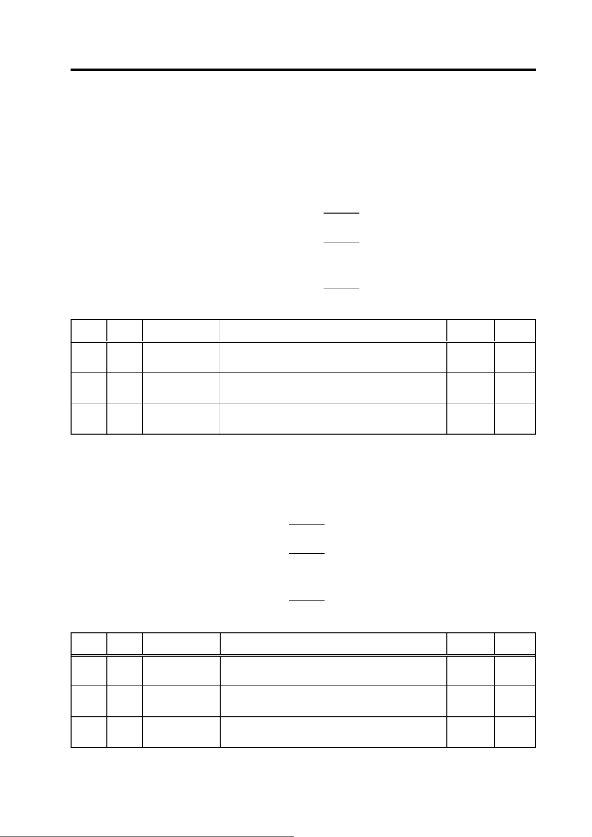
• Coil-specific orientation control position loop gain
Compensation magnification values are set for each coil by the SP119, SP120 and SP126
settings, relative to each coil's SP001 or SP002 position loop gain reference value. If a "0" is set,
the SP001 (SP002) setting is adopted.
SP119
Effective position loop gain (H-coil) = SP001 (SP002) ×
256
SP120
Effective position loop gain (L-coil) = SP001 (SP002) ×
256
<<Only for MDS-C1-SPM>>
SP126
Effective position loop gain (M-coil) = SP001 (SP002) ×
256
No. Abbr. Parameter name Details
Setting
range
Standard
SP119 MPGH Orientation control
position loop gain H
coil magnification
Set the compensation magnification of the orientation position
loop gain for the H coil.
0 to 2560
(1/256-fold)
0
SP120 MPGL Orientation control
position loop gain L
coil magnification
Set the compensation magnification of the orientation position
loop gain for the L coil.
0 to 2560
(1/256-fold)
0
SP126 MPGM Orientation position
loop gain M coil
magnification
<For MDS-C1-SPM>
Set the compensation magnification of the orientation position
loop gain for the M coil.
0 to 2560
(1/256-fold)
0
• Coil-specific orientation control deceleration rate
Compensation magnification values are specified for each coil by the SP121, SP122 and
SP127 settings, relative to each coil's SP006 deceleration rate reference value. If a "0" is set,
the SP006 setting is adopted.
SP121
Effective deceleration rate (H coil) = SP006 ×
256
SP122
Effective deceleration rate (L coil) = SP006 ×
256
<<Only for MDS-C1-SPM>>
SP127
Effective deceleration rate (M coil) = SP006 ×
256
No. Abbr. Parameter name Details
Setting
range
Standard
SP121 MPCSH Orientation
deceleration rate H
coil magnification
Set the compensation magnification of the orientation
deceleration rate for the H coil.
0 to 2560
(1/256-fold)
0
SP122 MPCSL Orientation
deceleration rate L
coil magnification
Set the compensation magnification of the orientation
deceleration rate for the L coil.
0 to 2560
(1/256-fold)
0
SP127 MPCSM Orientation
deceleration rate M
coil magnification
<For MDS-C1-SPM>
Set the compensation magnification of the orientation
deceleration rate for the M coil.
0 to 2560
(1/256-fold)
0