bnp-b2365(eng)b.pdf - 第265页
5. Spindle Adjustment 5 - 20 (4) Spindle control output 4 Name Details F E D C B A 9 8 7 6 5 4 3 2 1 0 ORF2 TLUA ATA OSPA PYVA SD2 MTC WRC F MKC SYSA ORCF ZS US SD1 CD bit Details 0 CD Current detection 1 SD1 Speed detec…

5. Spindle Adjustment
5 - 19
bitA. In forward run indexing (WRNA)
bitB. In reverse run indexing (WRIA)
The corresponding output signal turns ON while forward run indexing (WRN) or reverse run
indexing (WRI) is input to the spindle drive unit.
bitC. In orientation start command signal (ORCA)
This signal turns ON while the orientation start command (ORC) is input to the spindle drive unit.
bit D. L coil selected (LCSA)
This signal turns ON while the L coil selection signal (LCA) is input to the spindle drive unit.
<<For MDS-C1-SP>>
bitE. In sub-motor selection (MSA)
This signal turns ON when selecting sub-motor with 1-drive unit 2-motor specifica t ion.
<<For MDS-C1-SPM>>
bitE. In M coil selection (MCSA)
This signal turns ON when selecting medium-speed coil in case of using the medium-speed coil.
5. Spindle Adjustment
5 - 20
(4) Spindle control output 4
Name Details
F E D C B A 9 8 7 6 5 4 3 2 1 0
ORF2 TLUA
ATA
OSPA
PYVA
SD2 MTC
WRCF
MKC
SYSA
ORCF
ZS US SD1 CD
bit Details
0
CD
Current detection
1
SD1
Speed detection 1
2
US
Up-to-speed
3
ZS
Zero speed
4
ORCF
Orientation complete
5
SYSA
Synchronous speed match
6
MKC
Changing coil
7
WRCF
Index positioning completed
8
MTC
In changeover (for 1-drive unit 2-motor changeover)
9
SD2
Speed detection 2
A
B
PYVA
In minimum weak excitation value changeover
C
OSPA
Orientation speed changeover state
D
ATA
In automatic adjustment (only for MDS-C1-SPM)
E
TLUA
Spindle holding force increased
F
ORF2
2nd orientation completed
Spindle control output 4
bit0. Current detection (CD)
This signal turns ON when the start signal (forward run, reverse run, orientation) is ON, and the
current flowing to the motor is approx. 110% or more of the rating. (The motor output (current)
guarantee value is 120% of the rating.)
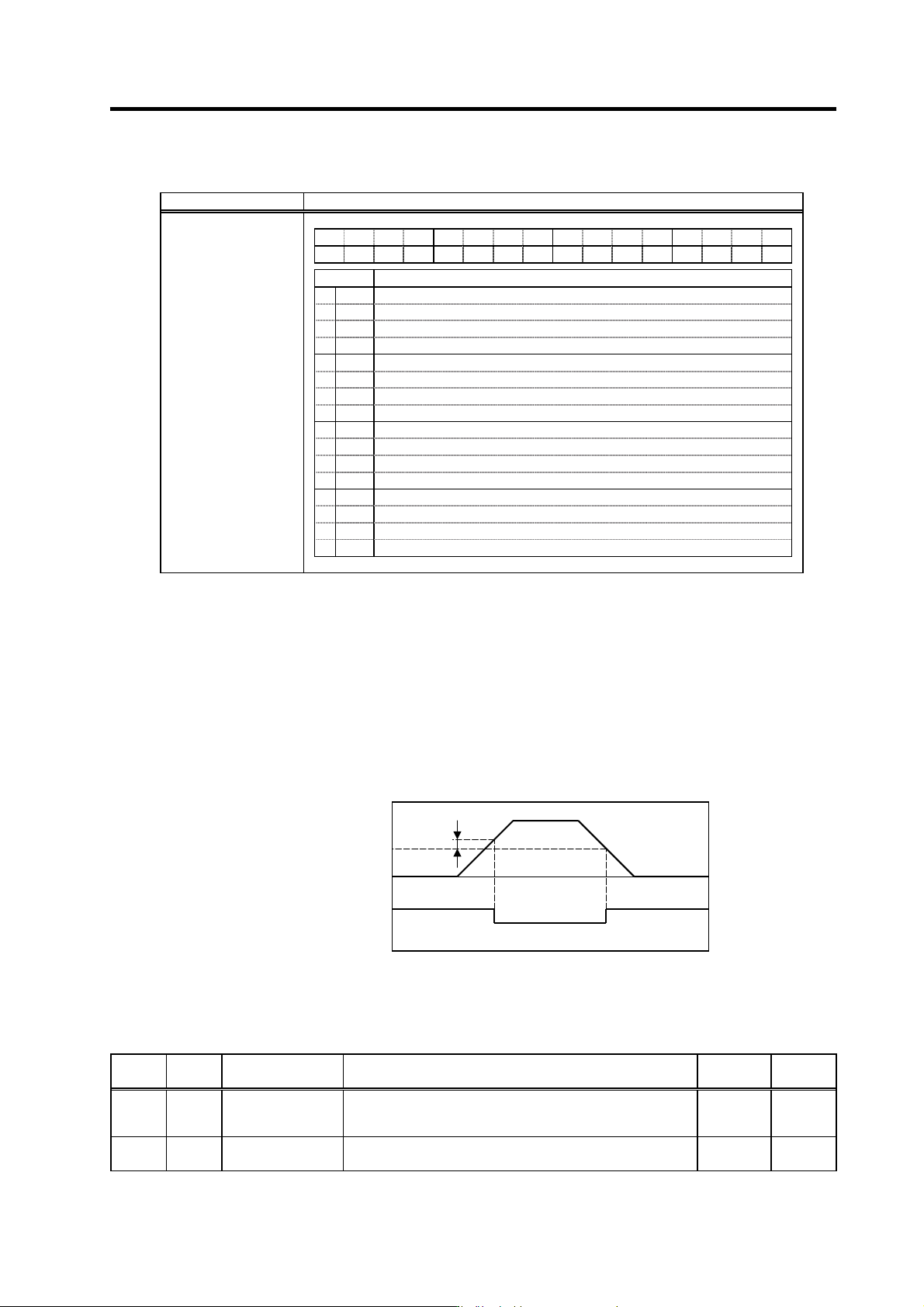
bit1. Speed detection 1 (SD1)
This signal turns ON when the motor speed drops below the value set with parameter SP020
(SDTS). The ON to OFF hysteresis width is set with parameter SP047 (SDTR). This signal turns
ON when the motor's speed is less than the set speed regardless of the input signal state.
Speed detection 1 (SD1) sequence
Related spindle parameters
No. Abbr. Parameter name Details
Setting
range
Standard
SP020 SDTS* Speed detection set
value
Set the motor speed for which speed detection output is
performed.
Usually, the setting value is 10% of SP017 (TSP).
0 to 32767
(r/min)
600
SP047 SDTR* Speed detection
reset value
Set the reset hysteresis width for a speed detection set value
defined in SP020 (SDTS).
0 to 1000
(r/min)
30
SP047
Motor speed
Speed detection 1 (SD1)
ON
OFF
SP020
0
5. Spindle Adjustment
5 - 21
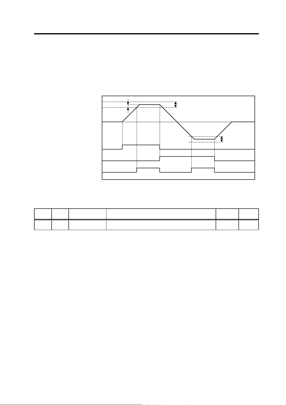
bit2. Up-to-speed (US)
This signal turns ON when the start command signal (forward run, reverse run) is ON, and the
motor speed has reached a range of ±15% (standard value) of the speed command value. This
signal turns OFF when the start command signal turns OFF. The up-to-speed output range can b e
set with the parameter SP048 (SUT). Even though the setting value is small, the output will be
±45r/min. Pay attention when speed command value is small.
Up-to-speed (US) sequence
Related spindle parameter
No. Abbr. Parameter name Details
Setting
range
Standard
SP048 SUT* Speed reach range Set the speed deviation rate with respect to the commanded
speed for output of the speed reach signal.
0 to 100
(%)
15
Motor speed
Forward run start command
(SRN)
ON
OFF
0
SP048
Reverse run start command
(SRI)
ON
OFF
Up-to-speed (US)
ON
OFF
Out
p
ut ran
g
e
(
minimum ±45r/min
)
Out
p
ut ran
g
e