bnp-b2365(eng)b.pdf - 第299页
5. Spindle Adjustment 5 - 54 5-3-5 Adjusting the C-axis control (1) Confirming the default parameters Confirm that the parameters are correctly set a ccording to the machine specifications. When carrying out interpolatio…
5. Spindle Adjustment
5 - 53
(5) Synchronous tap cutting operation
After adjusting the parameters, mount the tap and workpiece, and carry out actual cutting. Various
elements affect the tap cutting. Even if the synchronous accuracy (electrical accuracy) is good up
to this point, it may not enable cutting with a sufficient accuracy. Check the items in the following
table and improve the cutting accuracy.
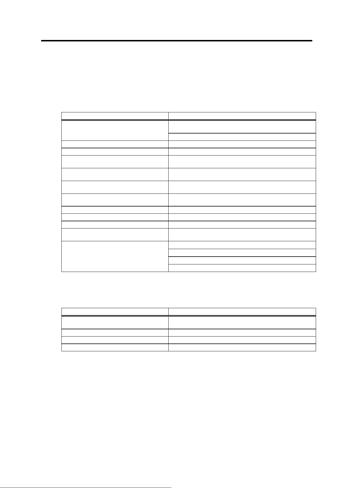
Investigation items for improving cutting accuracy
Investigation item Remedy
Use a spiral tape (recommended) with good cutting chip discharge
performance
1. The cutting chip discharge is poor (cutting
chips get caught)
Adjust the cutting speed to an appropriate value
2. The tap cutting performance is poor Replace the tap
3. The tap hole diameter is too large Set the tap hole diameter to an appropriate size
4. The spindle PLG waveform adjustment is
insufficient
Readjust the offset and gain
5. The servo axis backlash compensation
amount is incorrect
Adjust the backlash compensation amount
6. The servo axis pitch error compensation
amount is incorrect
Adjust the pitch error compensation amount
7. The acceleration/deceleration time constant is
short
Increase the acceleration/deceleration time constant to improve the
accuracy
8. The tap depth is too deep for the tap diameter Set the tap depth to up to 3-times the tap diameter
9. The spindle center deviates Check the tap mounting state
10. The spindle backlash is too large Improve the machine side
11. The spindle load inertia is too large (3-times or
more)
Try using fixed position loop excitation (SP193/bit3 = 1)
Note that vibration noise will be generated easily
12. The cutting load is large (50% or more)
The tap hole is too small → Check the tap mounting state
The spindle center deviates → Check the tap mounting state
The tap cutting performance is poor → Replace the tap
Try using fixed position loop excitation (SP193/bit3 = 1)
If the tap breaks, investigate the following items.
Investigation items when tap breaks
Investigation item Remedy
1. The program's screw pitch and tap pitch do not
match.
Set the program to the tap.
2. The tap center deviation is large Check the accuracy of the spindle and the tap mounting state
3. The tap hole is too shallow Drill the tap hole to an appropriate depth
4. The tap hole is too small Drill the tap hole to an appropriate size
5. Spindle Adjustment
5 - 54
5-3-5 Adjusting the C-axis control
(1) Confirming the default parameters
Confirm that the parameters are correctly set according to the machine specifications. When
carrying out interpolation control with the servo axis, set the following parameters according to the
servo axis specifications.
(a) Position loop gain
When carrying out interpolation control with the servo axis using C-axis control, the C-axis
control and position loop gain for each mode must be set to match the servo axis used for
interpolation control. During C-axis control in this case, the operation is always controlled with
the same position loop gain.
C-axis non-cutting position loop gain SP003 = SV003
First position loop gain for cutting on C-axis SP130 = SV003
Second position loop gain for cutting on C-axi s SP131 = SV003
Third position loop gain for cutting on C-axis SP132 = SV003
Stop position loop gain for cutting on C-axis SP133 = SV003
C-axis position loop gain 2 SP165 = SV004
C-axis position loop gain 3 SP166 = SV057
(b) High-gain servo synchronous compensation
Set C-axis control specification SP129/bit3 according to the specifications of the servo drive
unit used for interpolation control with C-axis control.
Synchronous compensation valid = High-gain servo:
MDS-C1-V1/V2 (for high-gain setting), MDS-B-V14/V24
Synchronous compensation invalid = Standard servo:
MDS-C1-V1/V2 (for st andard setting), MDS-B-V1/V2, MDS-B-SVJ2
(2) Gain parameters
The position loop gain and speed loop gain can be set according to each control state. Note that
when using SHG cont rol for C-axis control, or when carryin g out interpolation control with the servo
axis, the same value must be set in the position loop gain (SP003, SP130, SP131, SP132, SP133)
for each control state.
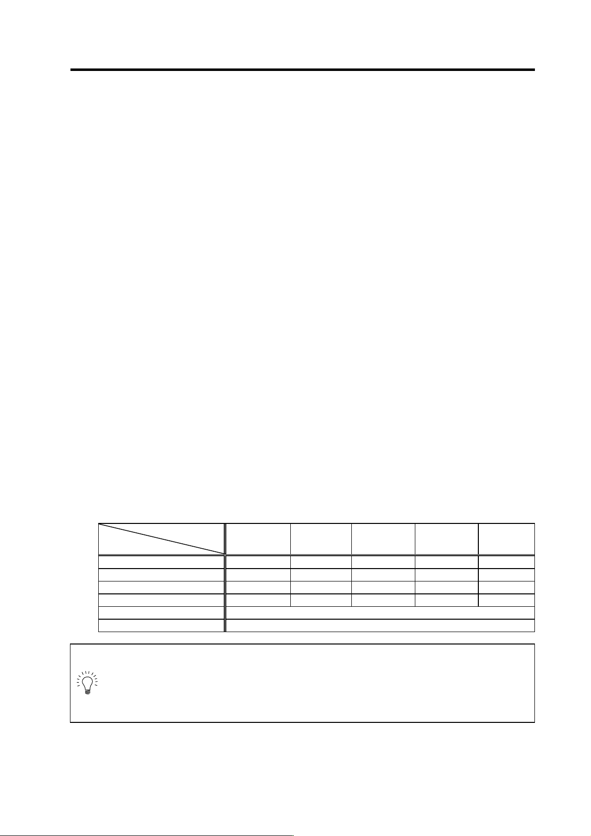
Gain parameter settings for C-axis control
Control state
Parameter
During
non-cutting
(rapid traverse)
No.1 gain
selection for
cutting control
No.2 gain
selection for
cutting control
No.3 gain
selection for
cutting control
When cutting
is stopped
Speed loop proportional gain SP134 SP137 SP140 SP143 SP146
Speed loop integral gain SP135 SP138 SP141 SP144 SP147
Speed loop delay compensation SP136 SP139 SP142 SP145 SP148
Position loop gain SP003 SP130 SP131 SP132 SP133
Position loop gain 2 SP165
Position loop gain 3 SP166
POINT
In order to perform C-axis interpolation with the servo axis, the position loop gain
settings for e a ch C-axis control mode must match that of the servo axis where
interpolation occurs. If the servo axis is performing SHG control, the SP165 and
SP166 settings apply to all control modes. Therefore, the position loop gain values
for each control mode (SP003, SP130, SP131, SP132 and SP133) must be th e same
as the position loop gain (SV003) for all the servo axes.
5. Spindle Adjustment
5 - 55
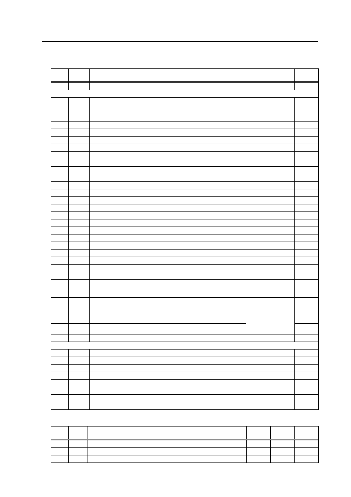
< Spindle parameters>
No. Abbr. Parameter name Unit
Setting
range
Standard
value
SP003 PGC0 C-axis non-cutting position loop gain rad/s 1 to 100 15
SP129 SPECC*
C-axis specifications
(The standard value is set according to the servo drive for interpolation
control.)
HEX
0000 to
FFFF
Standard:
0000
High-gain:
0008
SP130 PGC1 First position loop gain for cutting on C-axis rad/s 1 to 100 15
SP131 PGC2 Second position loop gain for cutting on C-axis rad/s 1 to 100 15
SP132 PGC3 Third position loop gain for cutting on C-axis rad/s 1 to 100 15
SP133 PGC4 Stop position loop gain for cutting on C-axis rad/s 1 to 100 15
SP134 VGCP0* C-axis non-cutting speed loop gain proportional item 0 to 5000 63
SP135 VGCI0* C-axis non-cutting speed loop gain integral item 0 to 5000 60
SP136 VGCD0* C-axis non-cutting speed loop gain delay advance item 0 to 5000 15
SP137 VGCP1* First speed loop gain proportional item for C-axis cutting 0 to 5000 63
SP138 VGCI1* First speed loop gain integral item for cutting on C-axis 0 to 5000 60
SP139 VGCD1* First speed loop gain delay advance item for cutting on C-axis 0 to 5000 15
SP140 VGCP2* Second speed loop gain proportional item for cutting on C-axis 0 to 5000 63
SP141 VGCI2* Second speed loop gain integral item for cutting on C-axis 0 to 5000 60
SP142 VGCD2* Second speed loop gain delay advance item for cutting on C-axis 0 to 5000 15
SP143 VGCP3* Third speed loop gain proportional item for cutting on C-axis 0 to 5000 63
SP144 VGCI3* Third speed loop gain integral item for cutting on C-axis 0 to 5000 60
SP145 VGCD3* Third speed loop gain delay advance item for cutting on C-axis 0 to 5000 15
SP146 VGCP4* Speed loop gain proportional item for stop of cutting on C-axis 0 to 5000 63
SP147 VGCI4* Speed loop gain integral item for stop of cutting on C-axis 0 to 5000 60
SP148 VGCD4* Speed loop gain delay advance item for stop of cutting on C-axis 0 to 5000 15
SP149 CZRN C-axis zero point return speed r/min 1 to 500 50
SP150 CPDT C-axis zero point return deceleration point 1 to 1000 1
SP151 CPSTL C-axis zero point return shift amount (low byte) 0000
SP152 CPSTH C-axis zero point return shift amount (high byte)
1/1000
deg
(HEX)
00000000
to
FFFFFFFF
0000
SP153 CINP C-axis in-position width
1/1000
deg
(HEX)
0000 to
FFFF
03E8
SP154 CODRL* Excessive error width on C-axis (low byte) D4C0
SP155 CODRH* Excessive error width on C-axis (high byte)
1/1000
deg
(HEX)
00000000
to
FFFFFFFF
0001
SP156 OVSH C-axis overshoot compensation 0.1% 0 to 1000 0
SP159 CPY0 C-axis non-cutting variable excitation ratio % 0 to 100 50
SP160 CPY1 C-axis cutting variable excitation ratio % 0 to 100 100
SP161 IQGC0* Current loop gain magnification 1 for non-cutting on C-axis % 1 to 1000 100
SP162 IDGC0* Current loop gain magnification 2 for non-cutting on C-axis % 1 to 1000 100
SP163 IQGC1* Current loop gain magnification 1 for cutting on C-axis % 1 to 1000 100
SP164 IDGC1* Current loop gain magnification 2 for cutting on C-axis % 1 to 1000 100
SP165 PG2C C-axis position loop gain 2 rad/s 0 to 999 0
SP166 PG3C C-axis position loop gain 3 rad/s 0 to 999 0
<Servo parameters>
No. Abbr. Parameter name Unit
Setting
range
Standard
value
SV003 PGN1 Position loop gain 1 rad/s 1 to 200 33
SV004 PGN2 Position loop gain 2 rad/s 0 to 999 0
SV057 SHGC SHG control gain rad/s 0 to 1200 0