bnp-b2365(eng)b.pdf - 第191页
3. Setup 3 - 104 3-6 Initial adjustment of the spindle PLG 3-6-1 Adjusting the PLG installation The PLG (spindle motor speed detector) mounted on the Mitsubishi framed spindl e motor is shipped from Mitsubishi in the adj…

3. Setup
3 - 103
<For MDS-C1-SP/SPH/SPX/SPHX>
No. Abbr. Parameter name Details
Setting range
(Unit)
Standard
setting
SP257
to
SP320
Motor constant
(H coil)
This parameter is valid only in the following two
conditional cases:
(a) In case that SP034 (SFNC2)/bit0=1
and SP034 (SFNC2)/bit2=0
Set the motor constants when using a special motor,
not described in the SP040 (MTYP) explanation and
when not using the coil changeover motor.
(b) In case that SP034 (SFNC2)/bit0=1
and SP034 (SFNC2)/bit2=1
Set the motor constant of the H coil of the coil
changeover motor.
(Note) It is not allowed for the user to change the setting.
(HEX setting)
0000 to FFFF 0000
SP321
to
SP384
Motor constant
(L coil)
This parameter is valid only in the following conditional
case:
(a) In case that SP034 (SFNC2)/bit0=1
and SP034 (SFNC2)/bit2=1
Set the motor constant of the L coil of the coil
changeover motor.
(Note) It is not allowed for the user to change the setting.
(HEX setting)
0000 to FFFF 0000
All motor constant parameters are validated with the NC power turned ON again.
<For MDS-C1-SPM>
No. Abbr. Parameter name Details
Setting range
(Unit)
Standard
setting
SP257
to
SP296
SP312
to
SP320
Motor constant
(H coil)
This parameter is valid only in the following two
conditional cases:
(a) In case that SP034 (SFNC2)/bit0=1
and SP034 (SFNC2)/bit2=0
Set the motor constants when using a special motor,
not described in the SP040 (MTYP) explanation and
when not using the coil changeover motor.
(b) In case that SP034 (SFNC2)/bit0=1
and SP034 (SFNC2)/bit2=1
Set the motor constant of the H coil of the coil
changeover motor.
(Note) It is not allowed for the user to change the setting.
(HEX setting)
0000 to FFFF 0000
SP297
to
SP311
SP363
to
SP375
Motor constant
(M coil)
This parameter is valid only in the following conditional
case:
(a) In case that SP034 (SFNC2)/bit0=1
and SP034 (SFNC2)/bit2=1
Set the motor constant of the M coil of the coil
changeover motor.
(Note) It is not allowed for the user to change the setting.
(HEX setting)
0000 to FFFF 0000
SP321
to
SP362
SP376
to
SP384
Motor constant
(L coil)
This parameter is valid only in the following conditional
case:
(a) In case that SP034 (SFNC2)/bit0=1
and SP034 (SFNC2)/bit2=1
Set the motor constant of the L coil of the coil
changeover motor.
(Note) It is not allowed for the user to change the setting.
(HEX setting)
0000 to FFFF 0000
All motor constant parameters are validated with the NC power turned ON again.
3. Setup
3 - 104
3-6 Initial adjustment of the spindle PLG
3-6-1 Adjusting the PLG installation
The PLG (spindle motor speed detector) mounted on the
Mitsubishi framed spindle motor is shipped from Mitsubishi
in the adjusted state. If there are no particular problems,
carry out automatic adjustment "3-6-2 Automatic
adjustment of Z phase" and "3-6-3 Automatic adjustment of
motor end PLG" according to the spindle system.
When using the spindle end PLG for simple C-axis control
or the built-in spindle, the PLG detector is installed by the
user, so the PLG sensor's gap and output signal must be
adjusted with the following procedures. After installing and
adjusting these, carry out automatic adjustment of the PLG
according to each system.
Install the PLG and then adjust following the procedures on
the right. The output signal waveform can be retrieved from
the check terminal on the PCB. Measure the waveform with
an oscilloscope. The A/B phase output signal and the Z
phase pulse width can be adjusted with the volume (VR1 to
VR5) on the PCB. (The pulse width has been adjusted at
shipment, and normally does not need to be adjusted.)
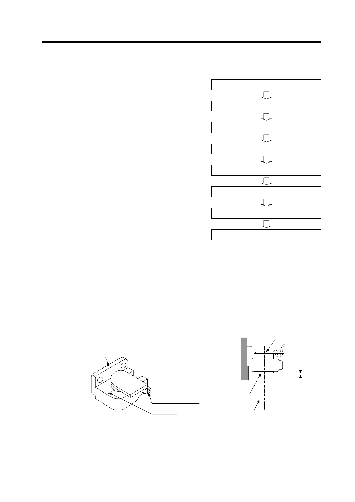
(1) Checking the gap
Check that the gap between the sensor detection surface and detection gear circumference is
within 0.15±0.01mm as shown below. The gap is adjusted before shipment, but an error could
occur due to the effect of the dimensional difference of the notched fitting section provided for
installation, or the dimensional difference of the detection gears' outer diameter. If deviated from
the above range, adjust the gap following the section "(2) Adjusting the gap".
Sensor section Gap with detection gear
(1) Checking the gap
(2) Adjusting the gap
(3) Checking the A and B phase output signal
(4) Adjusting the A and B phase output signal
(5) Checking the Z phase pulse width
(6) Adjusting the Z phase pulse width
(7) Checking the Z phase and A phase difference
(8) Adjusting the Z phase and A phase difference
Flow of PLG installation and adjustment
Senso
r
Detection gear
circumference
Ga
p
0.15±0.01mm
Detection gear
Sensor detection
surface
Markin
g
line
Sensor installation
seat
Sensor fixing screw
3. Setup
3 - 105
(2) Adjusting the gap
[1] Confirm that the detection gears are not rotating. The sensor could be damaged if the gap is
adjusted while the gears are rotating.
[2] Loosen the sensor fixing screw with the sensor fixed on the sensor installation seat.
[3] Using a clearance gauge, adjust so that the gap between the sensor detection surface and the
detection gears' circumference is 0.15±0.01mm.
[4] The sensor can be moved up and down or turned when the sensor fixing screw is loosened.
Position the rotating direction to match the marking line drawn on the sensor and installation
seat.
[5] When done adjusting the gap, apply a locking agent on the sensor fixing screw, and then fix
the sensor.
[6] After fixing the sensor, check the gap again. If operation is carried out with an excessively
small gap, the sensor and gears could contact, and the sensor could be damaged.
[7] Faults could occur if an excessive external force is applied or if the sensor detection surface is
damaged.
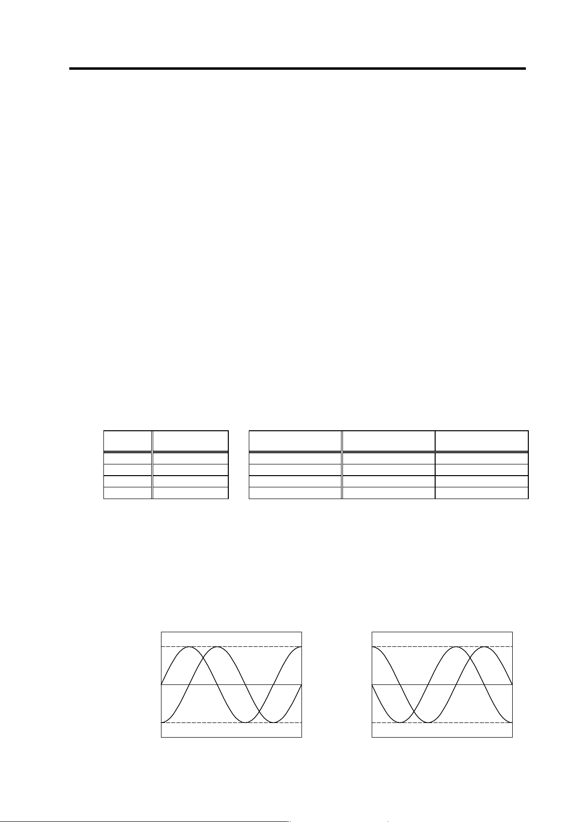
(3) Checking the A phase and B phase output signal
Check the output signal waveform by measuring the signals of the check terminals on the PCB
with the DC range of the synchroscope.
A phase output signal........ Across A-G
B phase output signal........ Across B-G
The PLG reference speed when confirming the output signal waveform differs according to the
number of output pulses. Refer to the following table for the reference speed for each number of
pulses. If operation is not possible at the reference speed, operate at a low speed within the range
in which the waveform can be confirmed.
Check terminal function
Reference speed for A and B p hase output signal confirmation
Check
terminal
Signal name
Number of detection
gear teeth
Number of A and B
phase pulses
Reference speed for
signal confirmation
A A phase 128 128 3600 r/min
B B phase 180 180 2500 r/min
Z Z phase 256 256 1800 r/min
G Ground 512 512 1200 r/min
The output signal waveform is confirmed when the motor is run in the forward direction and reverse
direction. The rotation directions are defined below.
During forward run ... When the detection gears are rotating in the clockwise direction looking
from the sensor lead side.
During reverse run ... When the detection gears are rotating in the counterclockwise direction
looking from the sensor lead side.
The normal A and B phase output signal waveform when running at the reference speed is shown
below. If the output signal waveform is not as shown below, refer to the next section "(4) Adjusting
the A and B phase output signal" and adjust.
A pha se/B phase output signal waveform
during forward run
A pha se/B phase output signal waveform
during reverse run
A phase
B
p
hase
1.45 ~ 1.55
Volta
g
e
[
V
]
-1.45 ~ -1.55
0
Time
A
p
haseB
p
hase
1.37 ~ 1.63
Volta
g
e
[
V
]
-1.37 ~ -1.63
0
Time