bnp-b2365(eng)b.pdf - 第71页
2. Wiring and Connection 2 - 32 (5) Connecting the simple C-axis control Refer to section (1) for connection with the spindle motor. G B Z A VR1 VR2 VR4 MDS-C1-SPX MDS-C1-SPHX S pindle motor MDS-B-PJEX S pind le end PLG …
2. Wiring and Connection
2 - 31
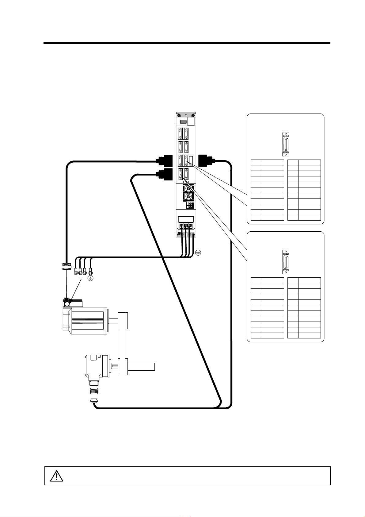
(4) Connecting the for C-axis detector
Refer to section (1) for connection with the spindle motor.
MDS-C1-SP
U VW
U V W
CN5
Spindle motor
C-axis detector
Power cable
CN7
Option cable : CNP7A
Option cable : CNP67A
CN6
Max. 30m
Option cable : CNP5
Spindle
Pin No.
Detector connector : CN6
No.1
No.10
No.11
No.20
Name
MA*
MB*
MZ*
Pin
11
12
13
14
15
16
17
18
19
20
Name
MA
MB
MZ
Pin
1
2
3
4
5
6
7
8
9
10
Pin No.
Detector connector : CN7
No.1
No.10
No.11
No.20
Name
LG
CA*
CB*
CZ*
LG
P5(+5V)
P5(+5V)
Pin
11
12
13
14
15
16
17
18
19
20
Name
LG
CA
CB
CZ
P5(+5V)
Pin
1
2
3
4
5
6
7
8
9
10
Supplement
1. The C-axis control function is connected to the CN7 connector.
2. When using both the C-axis control function and orient ation function, two cables (two-wire cable) are
connected from the detector.
3. The orientation signal connected to CN5 or CN6 can be connected to the NC with the differential
output from the CN8 connector.
CAUTION
The shield of spindle detector cable is not FG. Do not ground.
2. Wiring and Connection
2 - 32
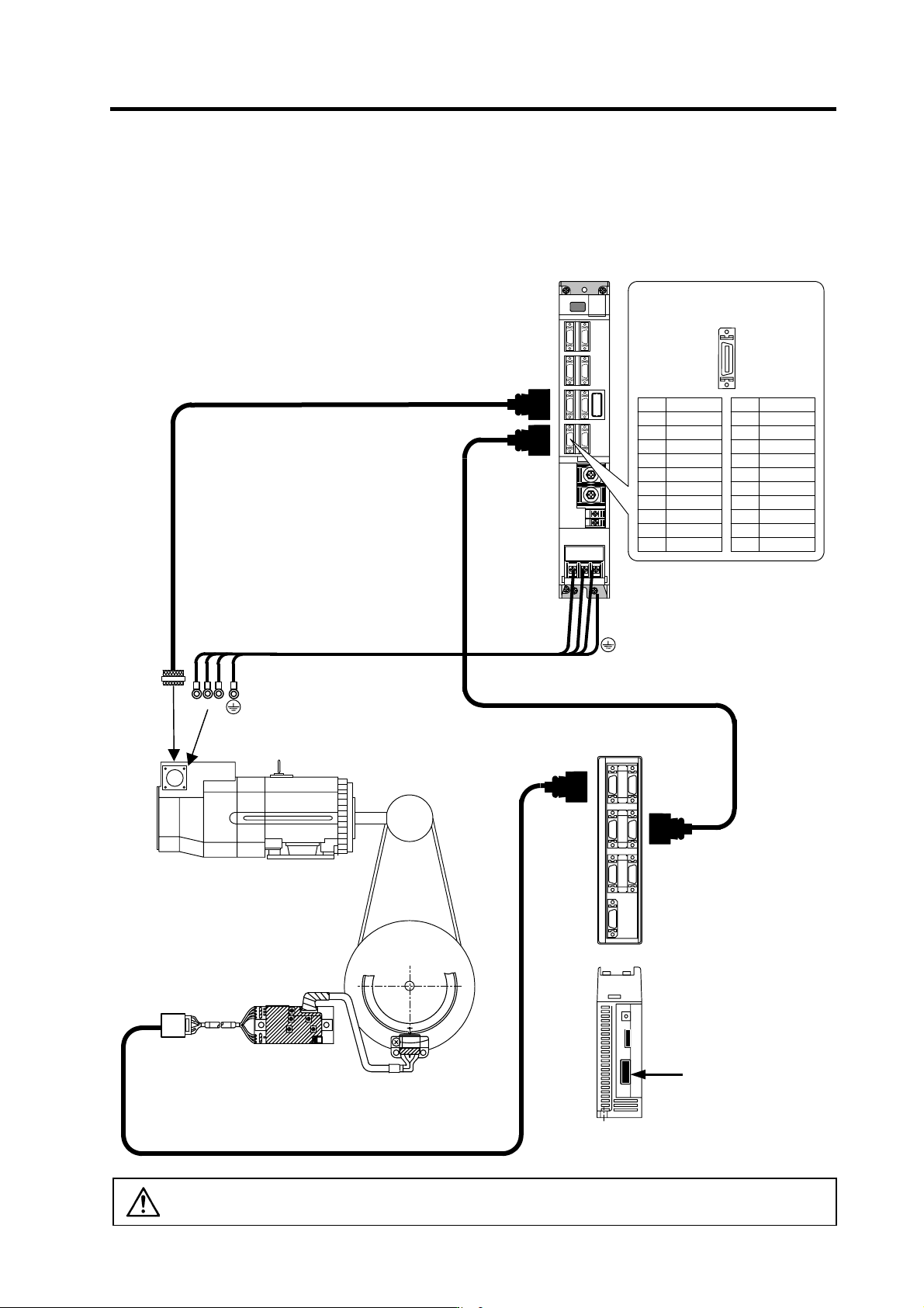
(5) Connecting the simple C-axis control
Refer to section (1) for connection with the spindle motor.
G
B
Z
A
VR1
VR2
VR4
MDS-C1-SPX
MDS-C1-SPHX
Spindle motor
MDS-B-PJEX
Spind le end PLG
Spindle
Motor axis
CN5
U
VW
U V W
Max. 30m
Option cable : CNP5
Power cable
CN7
CN5
CN8
24VDC
power
CR30
Bottom
SH21
CNP5
Pin No.
Detector connector : CN7
No.1
No.10
No.11
No.20
Name
LG
CA*
CB*
CZ*
LG
P5(+5V)
P5(+5V)
Pin
11
12
13
14
15
16
17
18
19
20
Name
LG
CA
CB
CZ
P5(+5V)
Pin
1
2
3
4
5
6
7
8
9
10
CAUTION
The shield of spindle detector cable is not FG. Do not ground.
2. Wiring and Connection
2 - 33
2-5 Connection of power supply
CAUTION
1. Make sure that the power supply voltage is within the specified range of each
unit. Failure to observe this could lead to damage or faults.
2. For safety purposes, always install a No-fuse breaker (NFB), and make sure
that the circuit is cut off when an error occurs or during inspections.
3. The wire size will differ according to each drive unit capacity.
4. For safety purposes, always install a magnetic contactor (contactor) on the
main circuit power supply input. Large rush currents will flow when the power
is turned ON.
5. A semiconductor element is used in the power supply unit's magnetic contact
drive circuit, and a surge absorber is installed to protect the element.
Therefore, a leakage current of approx. 15mA is passed. Confirm that the
exciting coil in the magnetic contact will not function at 15mA or less.