bnp-b2365(eng)b.pdf - 第41页
2. Wiring and Connection 2 - 2 DANGER 1. Wiring work must be done by a qualified technician. 2. Wait at least 15 minutes after tu rning the power OFF and check the voltage with a tester, etc., before starting wiring. Fai…

2. Wiring and Connection
2 - 1
2-1 Part system connection diagram........................................................................................................ 2-3
2-2 Main circuit terminal block/control circuit connector .......................................................................... 2-4
2-2-1 Names and applications of main circuit terminal block signals and control circuit connectors... 2-4
2-2-2 Connector pin assignment .......................................................................................................... 2-5
2-3 NC and drive unit connection ............................................................................................................. 2-8
2-4 Motor and detector connection......................................................................................................... 2-11
2-4-1 Connecting the servomotor ....................................................................................................... 2-11
2-4-2 Connecting the full-closed loop system..................................................................................... 2-18
2-4-3 Connecting the synchronous control system ............................................................................ 2-22
2-4-4 Connection of the spindle motor ............................................................................................... 2-28
2-5 Connection of power supply............................................................................................................. 2-33
2-5-1 Power supply input connection .................................................................................................. 2-34
2-5-2 Connecting the grounding cable ............................................................................................... 2-37
2-5-3 Main circuit control ..................................................................................................................... 2-38
2-6 Wiring of the motor brake................................................................................................................. 2-39
2-6-1 Wiring of the motor magnetic brake .......................................................................................... 2-39
2-6-2 Dynamic brake unit wiring ......................................................................................................... 2-41
2-7 Peripheral control wiring.................................................................................................................... 2-42
2-7-1 Input/output circuit wiring............................................................................................................ 2-42
2-7-2 Spindle coil changeover ............................................................................................................ 2-43
2-7-3 Wiring of an external emergency stop....................................................................................... 2-46
2. Wiring and Connection
2 - 2
DANGER
1. Wiring work must be done by a qualified technician.
2. Wait at least 15 minutes after turning the power OFF and check the voltage
with a tester, etc., before starting wiring. Failure to observe this could lead to
electric shocks.
3. Securely ground the drive units and servo/spindle motor.
4. Wire the drive units and servo/spindle motor after installation. Failure to
observe this could lead to electric shocks.
5. Do not damage, apply forcible stress, place heavy items on the cables or get
them caught. Failure to observe this could lead to electric shocks.
6. Always insulate the power terminal connection section. Failure to observe
this could lead to electric shocks.
CAUTION
1. Correctly and securely perform the wiring. Failure to do so could result in
runaway of the servo/spindle motor or injury.
2. Do not mistake the terminal connections.
Failure to observe this item could lead to ruptures or damage, etc.
3. Do not mistake the polarity ( + ,
- ). Failure to observe this item could lead to
ruptures or damage, etc.
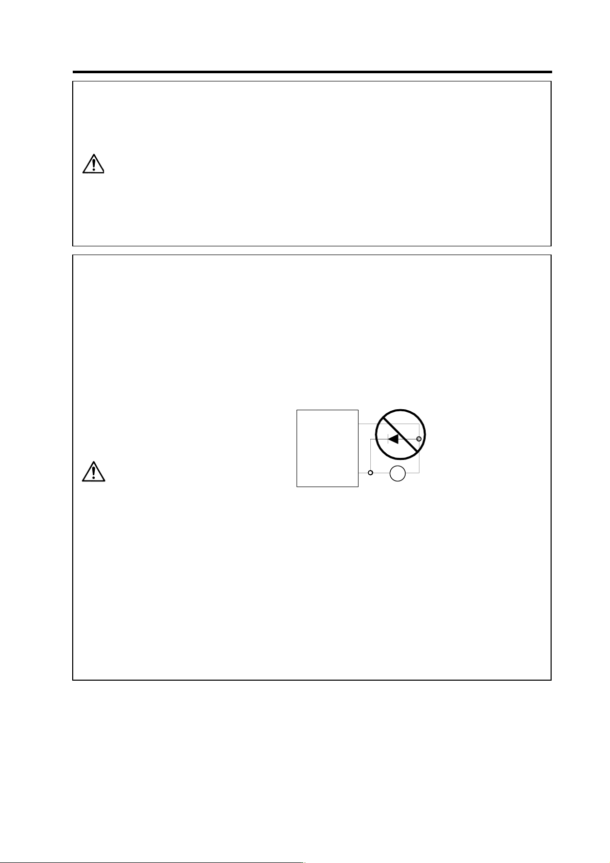
4. Do not mistake the direction of the diodes for the surge absorption installed
on the DC relay for the motor brake and contactor (magnetic contactor)
control. The signal might not be output when a failure occurs.
COM
(24V DC)
Con trol output signal
Servo dr ive u n it
RA
Servo drive unit
Control output signal
COM
(24VDC)
RA
5. Electronic devices used near the drive units may receive magnetic
obstruction. Reduce the effect of magnetic obstacles by installing a noise
filter, etc.
6. Do not install a phase advancing capacitor, surge absorber or radio noise
filter on the power line (U, V, W) of the servo/spindle motor.
7. Do not modify this unit.
8. The half-pitch connector (CN1A, etc.) on the front of the drive units have the
same shape. If the connectors are connected incorrectly, faults could occur.
Make sure that the connection is correct.
9. When grounding the motor, connect to the protective grounding terminal on
the drive units, and ground from the other protective grounding terminal.
(Use one-point grounding) Do not separately ground the connected motor
and drive unit as noise could be generated.
2. Wiring and Connection
2 - 3
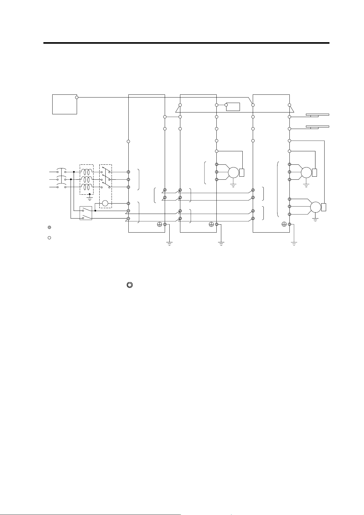
2-1 Part system connection diagram
MC1
Mitsubishi CN C
SV1,2
(CSH21)
External emergency
stop input
T
S
R
Contacto
r
No-fuse
breaker
Ground
: Main circuit
: Control circuit
CN1A
CN23
CN4
CN9
L1
L2
L3
L11
TE3
TE1
CN9
CN1B
L+
L-
U
V
W
CN6
CN5
TE1
PLG
Spindle drive unitPower supply unit
Spindle
motor
CN4
TE3
TE2
L+
L-
L11
L21
TE2
AC
reactor
Ground
Ground
L21
CN8
CN7
CN1A
CN4
CN9
CN20
CN1B
MU
MV
MW
CN2L
CN2M
LU
LV
LW
TE1
Motor end
detector
Motor end
detector
Battery unit
Servo drive unit
Servo
motor
Servo
motor
Tool end detecto
r
Tool end detecto
r
TE3
TE2
L+
L-
L11
L21
Ground
CN3M
CN3L
CN1A
MC
Breaker
SH21 cable
SH21 cable
(Note 1) The total length of the SH21 cable must be within 30m.
(Note 2) The connection method will differ according to the used motor.
(Note 3) When not using a battery unit, connect the terminal connector (R-TM).
(Note 4) The main circuit (
) and control circuit ({) are safely separated.