bnp-b2365(eng)b.pdf - 第50页
2. Wiring and Connection 2 - 11 2-4 Motor and detector connection 2-4-1 Connecting the servomotor (1) Connecting the HC52(B)/HC102(B)/HC152( B)/HC53(B)/HC103(B)/HC153(B)/HC103R(B) /HC153R(B)/HC203R(B) Pin Name A B C D E …
2. Wiring and Connection
2 - 10
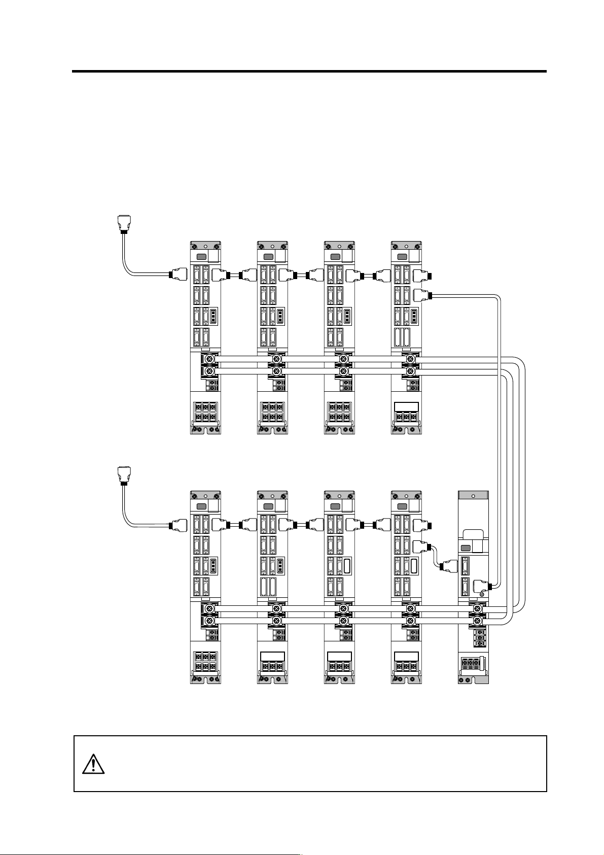
(3) When using one power supply shared unit by two NC communication bus systems
In systems employing a number of small-capacity drive units, a single power supply unit can be
shared by two NC communication bus systems. In this case, a power supply control axis must be
set for each axis of each NC communication bus.
For basic connection information, refer to "(1) When using one power supply unit".
Connections when using one power supply shared by two NC communication bus systems
CAUTION
If the two NC communication bus systems include a spindle drive unit, connect
the power supply unit's CN4 connector to the CN4 connector of the largest-
capacity spindle drive unit. If there is no spindle drive unit, connect to the
unbalance-axis servo drive unit.
MDS-C1-SP
12th axis
(CV control axis)
MDS-C1-V1
7th axis
(CV control axis)
CN1A
Connected to the NC
(System No.1)
MDS-C1-CV
(shared)
MDS-C1-V2
1st/2nd axis
CN1B CN1A
CN1B
CN4
CN4
MDS-C1-V2
3rd/4th axis
MDS-C1-V2
5th/6th axis
CN1B
CN1A
CN1B
CN1A
MDS-C1-V2
8th/9th axis
CN1B CN1A
MDS-C1-V1
10th axis
MDS-C1-SP
11th axis
CN1A
Connected to the NC
(System No.2)
CN1B
CN1A
CN1B
CN1A
CN1B
CN4
CN9
2. Wiring and Connection
2 - 11
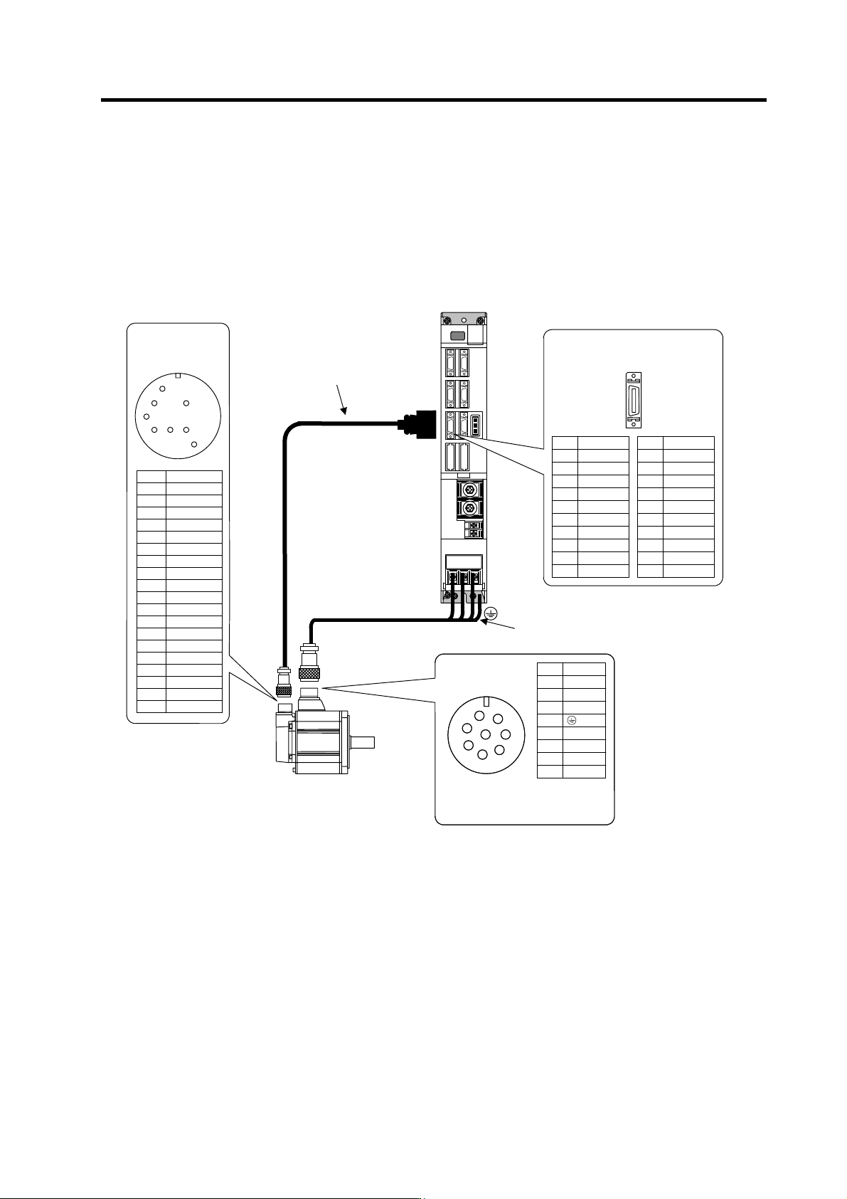
2-4 Motor and detector connection
2-4-1 Connecting the servomotor
(1) Connecting the HC52(B)/HC102(B)/HC152(B)/HC53(B)/HC103(B)/HC153(B)/HC103R(B)
/HC153R(B)/HC203R(B)
Pin Name
A
B
C
D
E BAT
F
G
H SD
J SD*
K RQ
L RQ*
M
N FG
P
R LG(GND)
S P5(+5V)
T
U
V
Detector connecto
r
MS3102A22-14P
E
J
K
H
N
L
R
S
MDS-C1-V1
U VW
Pin No.
Detector connector : CN2
No.1
No.10
No.11
No.20
Name
LG
SD*
RQ*
P5(+5V)
P5
(
+5V
)
Pin
11
12
13
14
15
16
17
18
19
20
Name
LG
SD
RQ
BAT
P5
(
+5V
)
Pin
1
2
3
4
5
6
7
8
9
10
A
B
C
H
F
E
D
G
B1 and B2 are brake terminals.
(Only for motor with brakes)
These are 24VDC, and have no
polarity.
Power connecto
r
CE05-2A22-23P
Name
U
V
W
Grounding
B1
B2
Pin
A
B
C
D
E
F
G
H
Option cable : CNV12
(Refer to Appendix 1 for details
on the cable tre atment.)
Max. 30m
Power wire and grounding wire
(Refer to Specification manual for details
on selecting the wire.)
CN2
2. Wiring and Connection
2 - 12
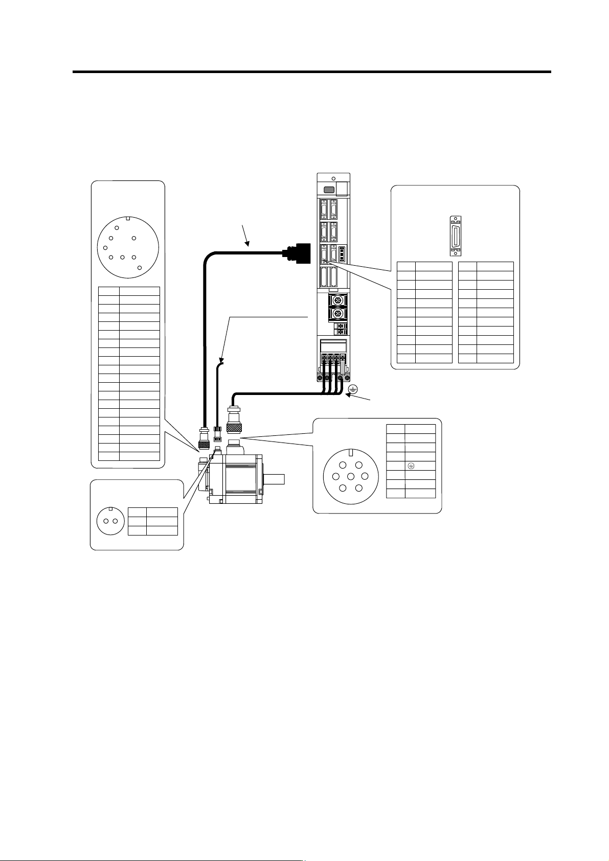
(2) Connecting the HC202(B)/HC352(B)/HC452(B)/HC203(B)/HC353(B)
Pin Name
A
B
C
D
E BAT
F
G
H SD
J SD*
K RQ
L RQ*
M
N FG
P
R LG(GND)
S P5(+5V)
T
U
V
MS3102A22-14P
E
J
K
H
N
L
R
S
MDS-C1-V1
U V W
Name
LG
SD*
RQ*
P5(+5V)
P5
(
+5V
)
Pin
11
12
13
14
15
16
17
18
19
20
Name
LG
SD
RQ
BAT
P5
(
+5V
)
Pin
1
2
3
4
5
6
7
8
9
10
CE05-2
A
24-10P
Name
U
V
W
Grounding
Pin
A
B
C
D
E
F
G
MS3102A10SL-4P
A
B
These are 24VDC, and have
no polarity.
Name
B1
B2
Pin
A
B
A
B
C
F
E
D
G
(Refer to section
"2-6 Wiring of the motor
brake" for details.)
Motor brake wiring
Detector connecto
r
Pin No.
Detector connector : CN2
No.1
No.10
No.11
No.20
Power connector
Option cable : CNV12
(Refer to Appendix 1 for details
on the cable tre atment.)
Max. 30m
Power wire and grounding wire
(Refer to Specification manual for details
on selecting the wire.)
CN2
Brake connecto
r