Utah-94-721002-System-Manual.pdf - 第101页
System Manual lñÑçêÇ=fåëíêìãÉåíë=mä~ëã~=qÉ ÅÜåçäçÖó== mä~ëã~ä~Ä póëíÉãNMM ii) STOP buttons: Select to stop either pumping down or venting the associated chamber. Note that the STOP button must be selected before venting …
mä~ëã~ä~ÄpóëíÉãNMM lñÑçêÇ=fåëíêìãÉåíë=mä~ëã~=qÉÅÜåçäçÖó== System Manual
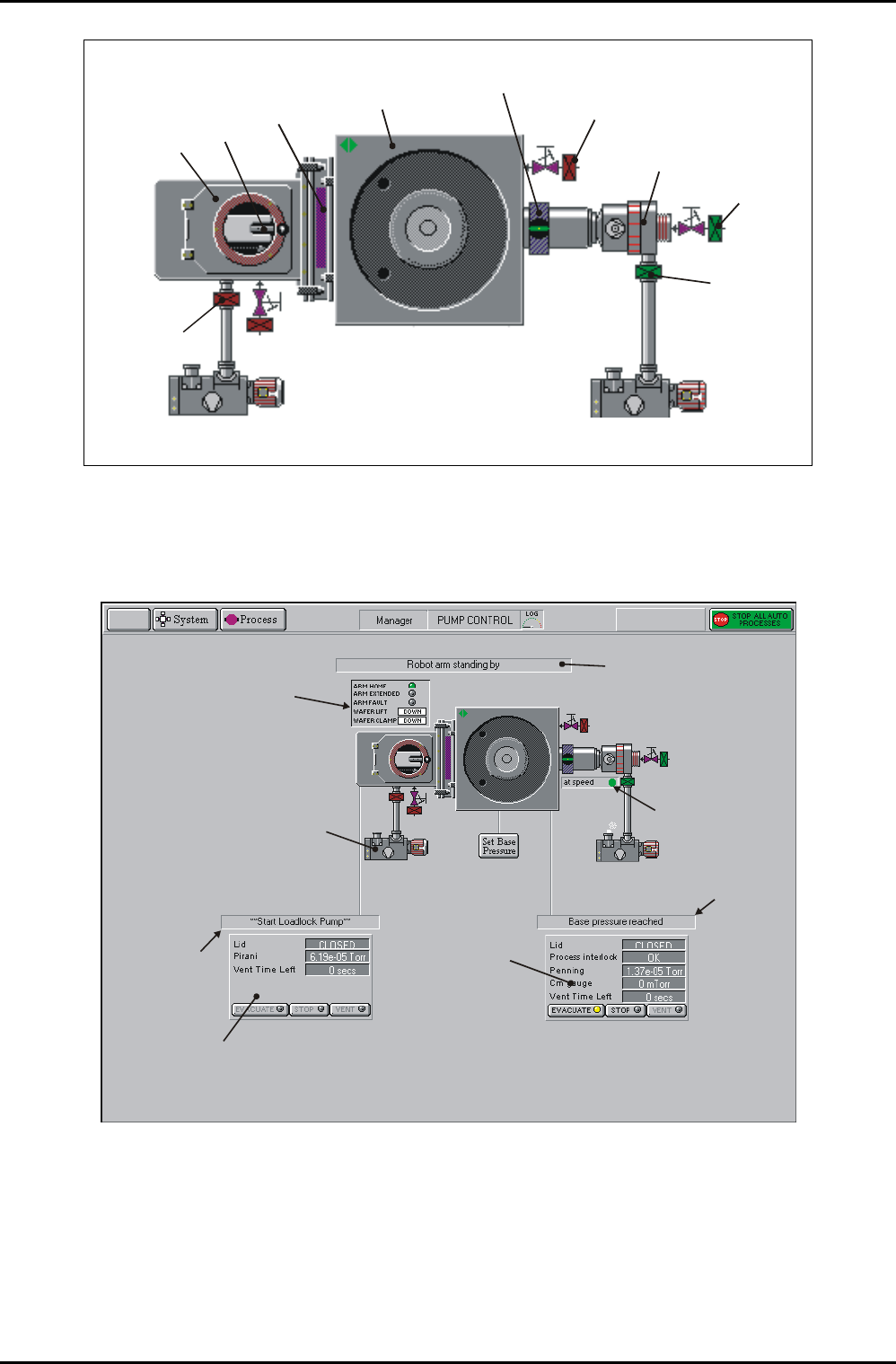
PROCESS
CHAMBER
AUTOMATIC
LOAD LOCK
WAFER
MIMIC
SLIT
VALVE
ROTARY VANE/DRY PUMP ROTARY VANE/DRY PUMP
A
UTOMATIC PRESSURE
CONTROLLER
BACKING
VALVE
ISOLATING
VALVE
TURBO
PUMP
TURBO
PURGE
VALVE
CHAMBER
VENT VALVE
Fig 5.11: Pump control page vacuum mimic
léÉê~íçê=áåíÉêÑ~ÅÉ=
The operator interface facilities are labelled in Fig 5.12.
Wafer transfer status
message field
Automatic load lock
status panel
Process
chamber
status panel
Click to start/stop
pump
Process chamber
message field
Automatic load lock
message field
Transfer arm,
wafer lift and
wafer clamp
status panel
Turbo ‘At Speed’
indicator (green
when at speed)
Fig 5.12: Pump control page operator interface
The following controls are provided:
a) Control and status panels for the process chamber and Automatic load lock. Each
Control and status panel has associated EVACUATE, STOP and VENT buttons.
i) EVACUATE buttons: Select to pump-down the associated chamber.
Operating Instructions
UC Davis 94-721001 Issue 1: March 06 Page 5-34 of 52 Printed: 22-Mar-06, 10:42

System Manual lñÑçêÇ=fåëíêìãÉåíë=mä~ëã~=qÉÅÜåçäçÖó== mä~ëã~ä~ÄpóëíÉãNMM
ii) STOP buttons: Select to stop either pumping down or venting the
associated chamber. Note that the STOP button must be selected before
venting to ensure the correct sequencing of the valves.
iii) VENT buttons: Select to vent the associated chamber.
b) Mimics of all valves showing open/closed status (coloured green when open, red
when closed).
c) Rotary/dry pump controls. Clicking on a rotary vane/dry pump mimic button will
switch the associated pump on or off (a running rotary pump is indicated by
animation).
d) Transfer arm, Wafer lift and Wafer clamp status panel. Displays indicators for ARM
HOME, ARM EXTENDED and ARM FAULT (illuminated when active). Also displays
WAFER LIFT and WAFER CLAMP status (up, down, moving or fault). See the
following table.
Message Meaning
UP The UP microswitch is detected as active.
DOWN The DOWN microswitch is detected as active.
MOVING Both microswitches are detected as inactive.
FAULT Both microswitches are detected as active.
e) The run status of the turbo pump is indicated by an associated message panel
containing an indicator. While the turbo pump is running up to speed, the message
‘accelerating’ is displayed and the indicator is flashing yellow. While the turbo pump
is at its operating speed, the message ‘at speed’ is displayed and the indicator is
green.
f) A SET BASE PRESSURE button. Select to set the Process Chamber Base Pressure.
g) Context related message panels for the process chamber, Automatic load lock and
wafer transfer progress.
h) ‘Ready for transfer’ indicators (WX) - displayed when the associated chamber or load
lock is evacuated and ready for wafer transfers.
Operating Instructions
Printed: 22-Mar-06, 10:42 Page 5-35 of 52 UC Davis 94-721001 Issue 1: March 06
mä~ëã~ä~ÄpóëíÉãNMM lñÑçêÇ=fåëíêìãÉåíë=mä~ëã~=qÉÅÜåçäçÖó== System Manual
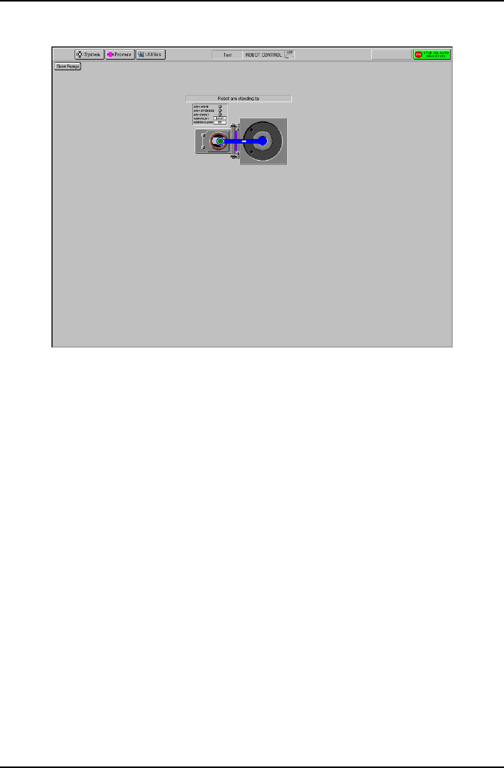
RKUKO= oçÄçí=Åçåíêçä=é~ÖÉ=
Fig 5.13: Robot control page
The Robot Control page is used to manually transfer a wafer between chambers (when
operating in automatic mode, i.e. running a recipe, wafers are transferred automatically). The
location of the wafer is indicated by a green wafer indicator. The arrowed path shows the
currently available wafer destination.
The page provides the following features:
Show Pumps
button
Displays the Pump Control page
Transfer arm
and Wafer lift
status panel
Displays indicators for ARM HOME, ARM EXTENDED and ARM FAULT
(illuminated when active). Also displays WAFER LIFT and WAFER CLAMP
status (up or down).
Transfer
status
message field
Displays context-related message about the wafer transfer progress.
Process
chamber and
Automatic load
lock mimic
Displays the wafer location and possible wafer destination.
To transfer a wafer from the Automatic load lock to the process chamber to carry out a
manual process, use the following steps:
1) Click on the Automatic load lock wafer mimic. The blue arrowed path is displayed
showing the available destination.
Operating Instructions
UC Davis 94-721001 Issue 1: March 06 Page 5-36 of 52 Printed: 22-Mar-06, 10:42