Utah-94-721002-System-Manual.pdf - 第285页
System Manual lñÑçêÇ=fåëí êìãÉåíë=mä~ëã~=qÉÅÜåçäçÖó== ^ää=lfmq=póëíÉãë SKP= `Ü~åÖáåÖ=íÜÉ=oc=ÅçãéçåÉåíë= This may be necessary to match a proces s beyond the normal operating range. WARNING HAZARDOUS RF VOLT AGE - CONTACT…

^ää=lfmq=póëíÉãë lñÑçêÇ=fåëíêìãÉåíë=mä~ëã~=qÉÅÜåçäçÖó== System Manual
SKO= iáåâ=pÉííáåÖë=
Incorrect link settings can cause the AMU to malfunction. The factory default settings are
given in the following table:
Link
Air
spaced
Capacitor
Low Power
Vacuum
Capacitor
High Power
Vacuum
Capacitor
Notes
LK1
A A A Setting A enables park position.
Setting B disables park.
LK2
B A B Coarse gain setting for C2 (‘A’ – low, ‘B’ –
medium, ‘c’ - high)
LK3
A A A Setting ‘B’ simulates RF on signal (for
testing only).
LK4
B A A Incremental Gain Signal. LK4 in position
‘A’ enables extra gain when in position
control. This is used when driving a
vacuum capacitor.
LK5
A A A Panel/PLC Controller. Position B for AMU
controlled by PLC
LK6
A A B Changes the biasing on the input
amplifier for C2 motor
LK7
B B A Changes the biasing on the input
amplifier for C2 motor
LK101
A A A Setting ‘A’ enables park position.
Setting ‘B’ disables park.
LK102
B A B Coarse gain setting for C1 (‘A’ – low, ‘B’ –
medium, ‘C’ - high)
LK104
B A A Incremental Gain Signal. LK104 in position
‘A’ enables extra gain when in position
control. This is used when driving a
vacuum capacitor.
LK105
A A A Panel/PLC Controller. Position ‘B’ for AMU
controlled by PLC
LK106
A A B Changes the biasing on the input
amplifier for C1 motor
LK107
A A B Changes the biasing on the input
amplifier for C1 motor
OIPT Automatch Unit
Issue 6: February 05 Page 18 of 20 Printed: 5-Jan-06, 8:03
System Manual lñÑçêÇ=fåëíêìãÉåíë=mä~ëã~=qÉÅÜåçäçÖó== ^ää=lfmq=póëíÉãë
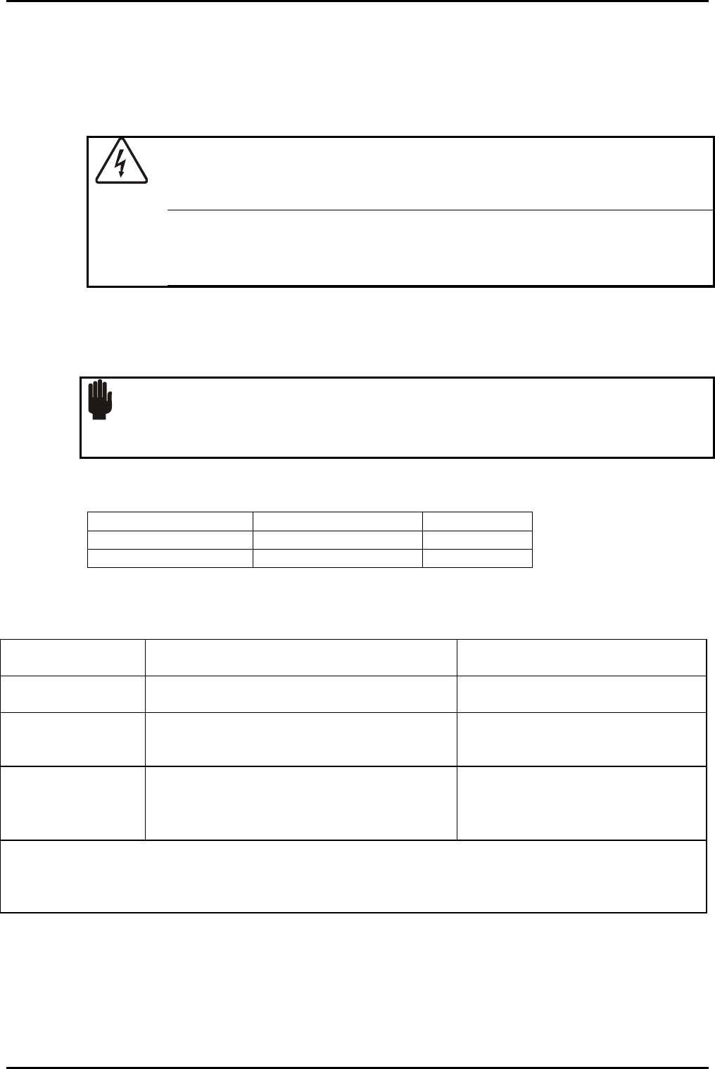
SKP= `Ü~åÖáåÖ=íÜÉ=oc=ÅçãéçåÉåíë=
This may be necessary to match a process beyond the normal operating range.
WARNING
HAZARDOUS RF VOLTAGE - CONTACT CAN CAUSE DEATH, SEVERE INJURY
OR BURNS
Any work requiring the removal of covers or panels must only be
performed by authorised personnel who are aware of the hazards
involved.
Turn off the RF generator completely before removing the smaller L-section cover. This
reveals the ends of the two variable capacitors and mounting positions for extra fixed
capacitors.
CAUTION
Components fitted must be suitable for RF power service. Low power circuit
devices will overheat quickly.
Suitable components are given in the following table:
OIPT Part Number Capacitance Rating
94-ECC1209 90pf 1kV
94-ECC1218 180pF 2kV
Change components according to the following table:
C1 going maximum
Add fixed capacitance in parallel with C1
See following NOTE.
C1 going minimum
Remove fixed capacitance in parallel with C1 Minimum is zero
C2 going maximum
1. Add fixed capacitance in parallel with C2
2. Increase coil inductance
See following NOTE.
C2 going minimum 1. Remove fixed capacitance in parallel
with C2
2. Decrease coil inductance
Minimum is zero fixed capacitance
NOTE: Variable capacitors C1 and C2 have a maximum capacitance of 1000pF and 500pF respectively.
For each of these variable capacitors there are three positions for fitting parallel ‘padding’
capacitors. Therefore, a maximum of 3 x 180pF padding capacitors could be fitted but usually
there is no need to fit more than one padding capacitor (i.e. 180pF).
OIPT Automatch Unit
Printed: 5-Jan-06, 8:03 Page 19 of 20 Issue 6: February 05

^ää=lfmq=póëíÉãë lñÑçêÇ=fåëíêìãÉåíë=mä~ëã~=qÉÅÜåçäçÖó== System Manual
SKQ= ^ÇàìëíãÉåí=çÑ=Å~é~Åáíçê=é~êâ=éçëáíáçåë=
The capacitors drive automatically to the park positions if:
the AMU is set to Auto
the RF is off
the circuit board links enable parking
The park positions can be adjusted when all of these conditions are satisfied, by altering the
corresponding potentiometer with a small flat-bladed screwdriver. The capacitor will move
when the potentiometer is adjusted, and the park position is displayed as the capacitor
position.
TK= lfmq=äçÅ~íáçåë=ïçêäÇïáÇÉ=
UK
Oxford Instruments Plasma Technolgy
North End, Yatton,
Bristol, BS49 4AP
Tel: +44(0)1934 837000
Fax: +44(0)1934 837001
Email:
plasma.technology@oxinst.co.uk
Web: www.oxford-
instruments.com/plmchp5.htm
USA
Oxford Instruments Inc.
130A Baker Avenue Extension
Concord, MA 01742
Tel: +1 978 369 9933
Toll Free +1 800-447-4717
Fax: +1 978 369 8287
Email:
info@ma.oxinst.com
Germany
Oxford Instruments GmbH
Otto-von-Guericke Ring 10,
D-65205 Wiesbaden
Tel: +49(0)6122 937161
Fax: +49(0)6122 937175
Email:
plasma@oxford.de
Japan
Oxford Instruments K.K.
2-11-6 Tomioka
Koto-ku, Tokyo 135-0047
Tel: +81-3-5245-3261
Fax: +81-3-5245-4466
Email:
oikkpt@oxinst.co.jp
Web: www.oxford-instruments.jp
People’s Republic of China (Beijing)
Oxford Instruments China
Room 714, Office Tower 3,
Henderson Center,
No. 18 Jianguomennei Ave,
Dongcheng District,
Beijing 100005
Tel: +86 106518 8160/1/2
Fax: +86 106518 8155
Email:
ptsales@oichina.cn
Web: www.oxford-instruments.com.cn
People’s Republic of China
(Shanghai)
Oxford Instruments China
Room 14-F, No.1 Plaza
800 Nanjing East Road
Shanghai 200001
Tel: +86 216360 8530
Fax: +86 216360 8535
Email:
ptsales@oichina.cn
Web: www.oxford-instruments.com.cn
Singapore
Oxford Instruments Pte. Ltd
371 Beach Road,
#02-07 Keypoint
Singapore 199597
Tel: +65 6337 6848
Fax: +65 6337 6286
Email:
oipt.sales@oxford-
instruments.com.sg
Taiwan
Oxford Instruments Overseas
Marketing Ltd.
1F, No 23 Jing-Shang 19
th
Street,
Hsinchu, Taiwan
Tel: +65 6337 6848
Fax: +65 6337 6286
Email:
oipt.sales@oxford-
instruments.com.sg
OIPT Automatch Unit
Issue 6: February 05 Page 20 of 20 Printed: 5-Jan-06, 8:03