Utah-94-721002-System-Manual.pdf - 第55页
System Manual lñÑçêÇ=få ëíêìãÉåíë=mä~ëã~=qÉÅÜåçäçÖó== mä~ëã~ä~ Ä póëíÉã=NMM The automatic load lock, shown in Fig 3.8, enables wafer loading and unloading to be automatically achieved under vacuum. These oper ations are …
mä~ëã~ä~Ä póëíÉã=NMM lñÑçêÇ=fåëíêìãÉåíë=mä~ëã~=qÉÅÜåçäçÖó== System Manual
PKNM= VQJNMMJNMJMR`=páåÖäÉ=ï~ÑÉê=~ìíçã~íáÅ=äç~Ç=äçÅâ==
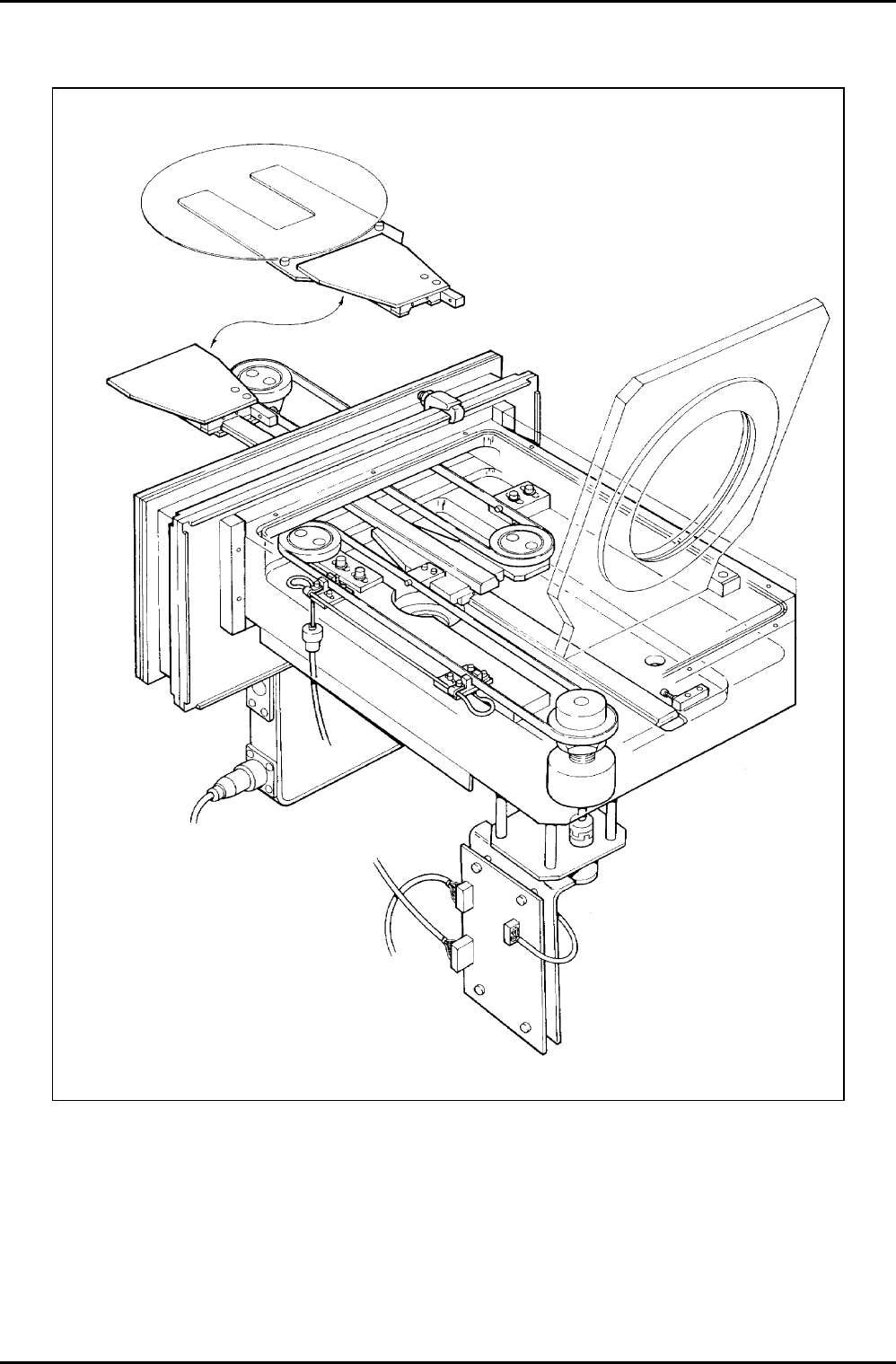
Fig 3.8: Single wafer automatic load lock
Description
UC Davis 94-721001 Issue 1: March 06 Page 3-18 of 22 Printed: 22-Mar-06, 7:29
System Manual lñÑçêÇ=fåëíêìãÉåíë=mä~ëã~=qÉÅÜåçäçÖó== mä~ëã~ä~Ä póëíÉã=NMM
The automatic load lock, shown in Fig 3.8, enables wafer loading and unloading to be
automatically achieved under vacuum. These operations are controlled by computer,
requiring minimum operator involvement. The Oxford Instruments Plasma Technology design
results in a very compact load lock (395 mm long with 400 mm of wafer support travel). The
load lock is capable of handling MESC
1
standard wafers up to 200 mm diameter.
PKNMKN= t~ÑÉê=íê~åëÑÉê=ãÉÅÜ~åáëã=çéÉê~íáåÖ=éêáåÅáéäÉ=
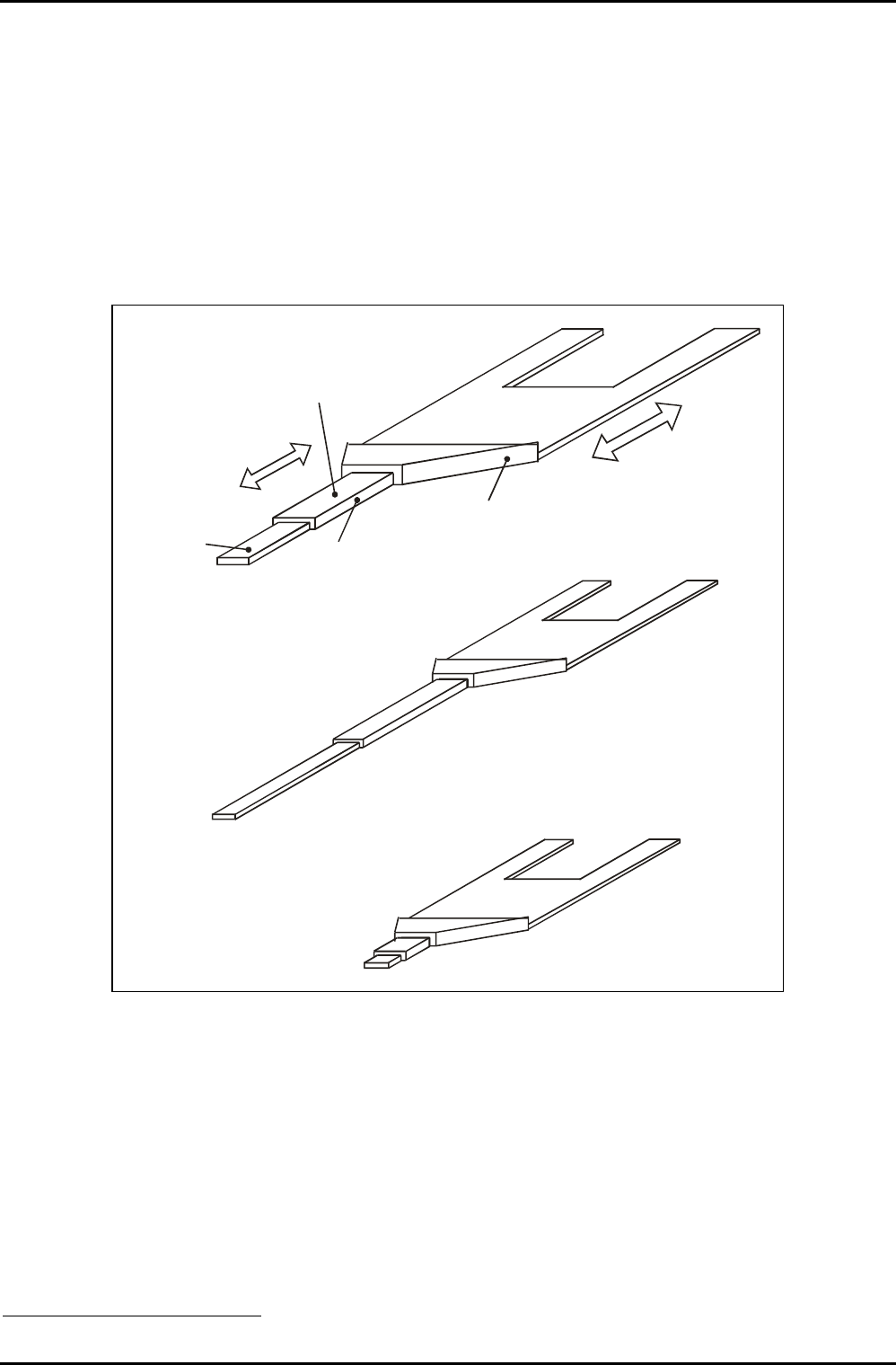
The operating principle of the automatic load lock wafer transfer mechanism is shown in Fig
3.9. This simplified illustration shows the three major components of the mechanism: the
fixed track, the carriage and the wafer support.
CARRIAGE RUNS
ALONG THE
FIXED TRACK
TRACK FIXED TO
LOAD LOCK
BASEPLATE
WAFER SUPPORT
RUNS ALONG THE
TRACK ON THE TOP
OF THE CARRIAGE
TRACK ON TOP OF
CARRIAGE
WAFER TRANSPORT MECHANISM
FULLY EXTENDED
WAFER TRANSPORT MECHANISM
FULLY RETRACTED
Fig 3.9: Simplified wafer transport mechanism operation
The fixed track is mounted on the load lock's baseplate and provides the bearing surface on
which the carriage runs. The carriage also has a top bearing surface on which the wafer
support runs.
When the mechanism is driven, the carriage runs along the fixed track and the wafer support
runs along the carriage's track simultaneously. This enables the wafer support to travel from
its fully retracted position (entirely contained in the load lock) to its fully extended position
(wafer load/unload position in the processing chamber).
1
Modular Equipment Standards Committee
Description
Printed: 22-Mar-06, 7:29 Page 3-19 of 22 UC Davis 94-721001 Issue 1: March 06
mä~ëã~ä~Ä póëíÉã=NMM lñÑçêÇ=fåëíêìãÉåíë=mä~ëã~=qÉÅÜåçäçÖó== System Manual
PKNMKO= cìåÅíáçå~ ä =aÉëÅêáéíáçå=
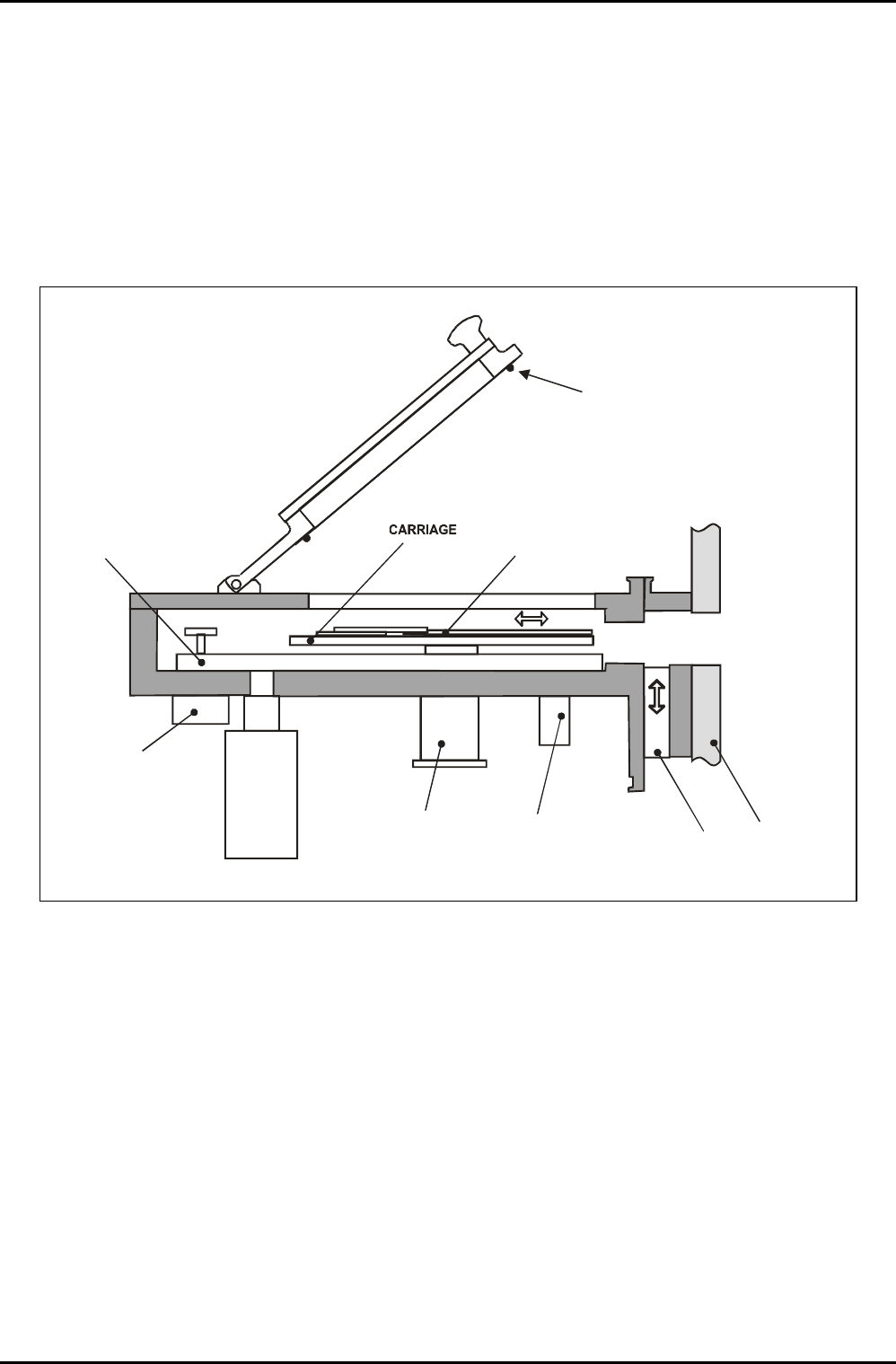
The load lock, shown in Fig 3.10, is fabricated from aluminium and incorporates a hinged lid
containing a view port. The chamber is pumped by a rotary pump or a turbomolecular pump
with the pressure being detected by an appropriate vacuum gauge mounted on the chamber
base plate. A pneumatically operated gate valve enables the load lock chamber to be isolated
from the processing chamber.
The wafer is transported from the load lock into the processing chamber on a wafer support,
which runs on a carriage, which in turn runs on a track.
VACUUM
GAUGE
PUMPING
PORT
FEEDTHROUGH
FOR WIRING
TO PHOTO DIODES
DC MOTOR
AND
REDUCTION
GEAR BOX
TRACK
WAFER
SUPPORT
PNEUMATIC
GATE VALVE
CHAMBER
SEAL
Fig 3.10: Automatic load lock, side view
The wafer transport mechanism, shown in Fig 3.9, comprises the following main components:
a) A Direct Current (DC) motor and associated reduction gearbox located outside the
load lock with the drive shaft entering the load lock through a vacuum seal.
b) Two steel belts each carried by two pulley wheels.
c) A track fixed to the load lock baseplate.
d) A carriage, which runs linearly along the track. The carriage is attached to Steel
Belt 1.
e) A wafer support mounted on the carriage. The wafer support runs linearly along the
carriage and is attached to Steel Belt 2.
Description
UC Davis 94-721001 Issue 1: March 06 Page 3-20 of 22 Printed: 22-Mar-06, 7:29