Utah-94-721002-System-Manual.pdf - 第111页
System Manual lñÑçêÇ=fåëíêìãÉåíë=mä~ëã~=qÉ ÅÜåçäçÖó== mä~ëã~ä~Ä póëíÉãNMM RKUKS= iÉ~â=ÇÉíÉÅíáçå=é~ÖÉ= Fig 5.17: Leak detection page The leak detection page, accessed fro m the Chamber 1 process page by sele cting the Lea…
mä~ëã~ä~ÄpóëíÉãNMM lñÑçêÇ=fåëíêìãÉåíë=mä~ëã~=qÉÅÜåçäçÖó== System Manual
Process gas pod
mimic
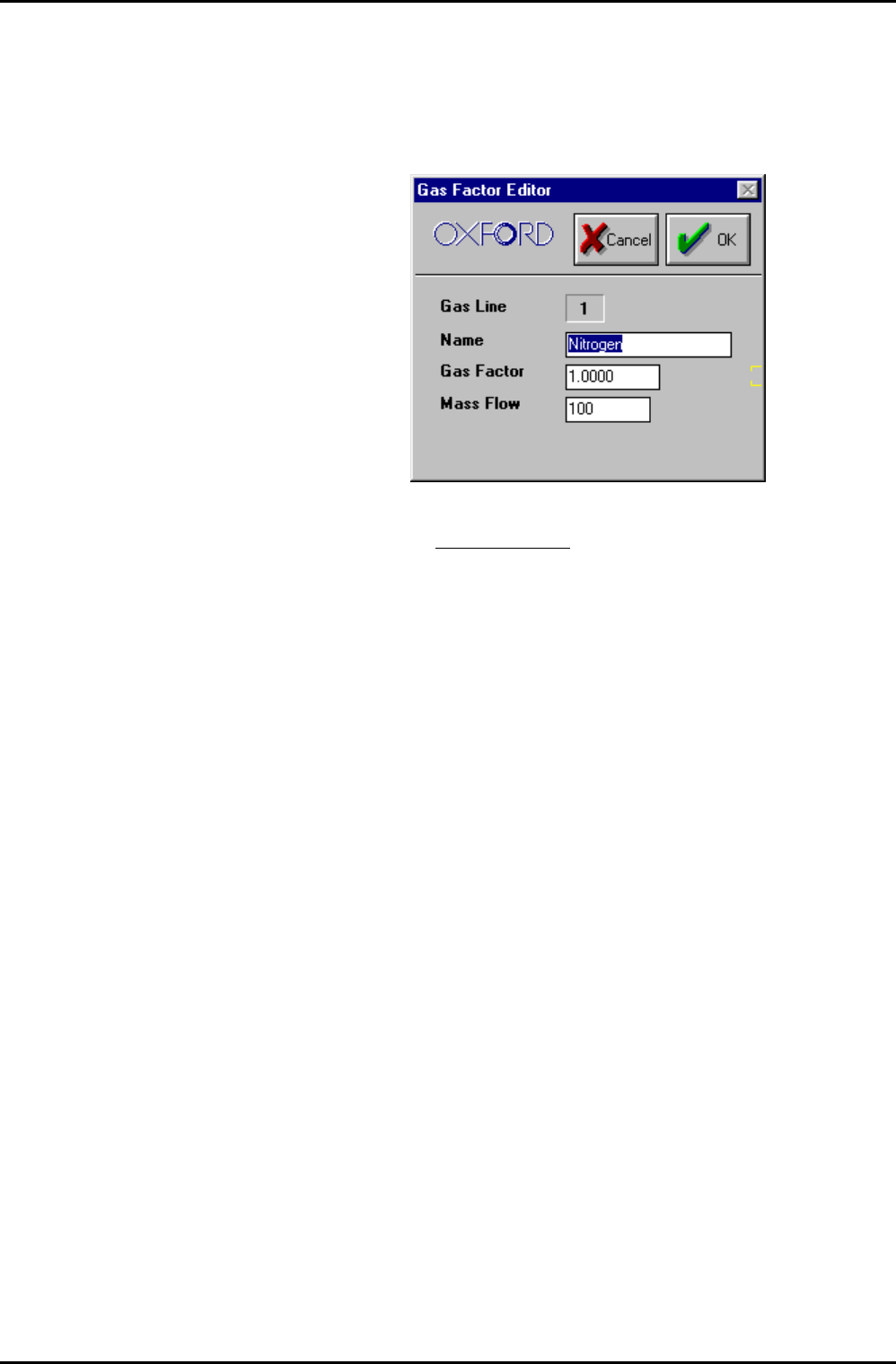
Displays a mimic of the gas lines installed in the gas pod.
Enter the required gas flow in sccm for each gas line. Click on the Gas
Name in an MFC mimic to edit the associated Gas Factors; the
following dialogue is displayed.
It is recommended to keep the Gas Factor as 1, and to put the full
scale of the MFC
for the gas used in the Mass Flow field.
For example, if Argon is used with a 100 sccm N
2
MFC. Put gas factor 1
and Mass Flow 141 sccm.
Operating Instructions
UC Davis 94-721001 Issue 1: March 06 Page 5-44 of 52 Printed: 22-Mar-06, 10:42
System Manual lñÑçêÇ=fåëíêìãÉåíë=mä~ëã~=qÉÅÜåçäçÖó== mä~ëã~ä~ÄpóëíÉãNMM
RKUKS= iÉ~â=ÇÉíÉÅíáçå=é~ÖÉ=
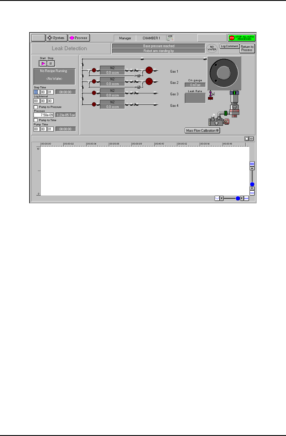
Fig 5.17: Leak detection page
The leak detection page, accessed from the Chamber 1 process page by selecting the Leak
Detection button, allows you to perform automatic or manual leak detection runs.
The Leak Detection page for a process chamber can be used to check the rate-of-pressure rise
in a sealed chamber. The chamber is first pumped (either for a fixed time, or to a given
pressure). The chamber then seals and the pressure rise rate is calculated. A graph of the
chamber pressure against time is plotted. The test stops either when a test time elapses, or
when the pressure gauge reaches full scale. The chamber is returned to pumping at the end
of the test.
The rate-of-pressure rise will depend on:
a) The leak rate from atmosphere. Leaks are not improved by more pumping.
b) The outgassing rate from all surfaces.
c) The ‘virtual leak’ rate from parts of the system furthest from the vacuum pump,
especially gas feed pipes.
Outgassing and virtual leaks are reduced by more pumping. Outgassing is increased if the
temperature of the whole system is raised.
The facilities available on this page are:
Page function
title field
Displays the current function of the page, i.e. Leak Detection
Process chamber
message field
Displays context related messages about the process chamber.
Operating Instructions
Printed: 22-Mar-06, 10:42 Page 5-45 of 52 UC Davis 94-721001 Issue 1: March 06

mä~ëã~ä~ÄpóëíÉãNMM lñÑçêÇ=fåëíêìãÉåíë=mä~ëã~=qÉÅÜåçäçÖó== System Manual
Transfer status/
Log Comment
message field
Displays context related messages about wafer transfer status. This
field is also used to enter comments about the current process run
which can be viewed on the log viewer page.
Wafer status
field
Displays context related messages about the currently selected wafer.
Log Comment
button
Allows comments about the current process to be entered in the
Transfer status/Log Comment message field. While entering a
comment, the button title changes to OK to allow the comment to be
accepted.
Return to
Process button
Select to return to the Chamber 1 or Chamber 2 process page.
Start button
Select to commence a leak detection test.
Stop button
Select to halt a leak detection test and return to pumping.
Recipe message
field
Displays information about the current recipe, step, loaded wafer
identity etc.
Step Time fields
Enter the required step time (in hours:minutes:seconds) for the
duration of the pressure-rise test. While a process is running, the
adjacent field displays the time remaining to the end of the step.
Log Interval
fields
Enter the sampling rate for the datalogging log file (in
hours:minutes:seconds).
If set to zero, no data log will be made.
Pump to
Pressure
checkbox
Select to cause the initial pumpdown to continue until a given
pressure is reached. The step will remain active until this condition is
met. (9Indicates selected). All setpoints are automatically set to zero,
except for base pressure. See the NOTE at the end of this sub-section.
Pressure fields
Enter the required Process Chamber target pressure. The measured
pressure is displayed in the adjacent field.
Pump to time
checkbox
Select to give the initial pumpdown a fixed duration. See the NOTE at
the end of this sub-section.
Pump Time
Duration of initial pumpdown (in hours:minutes:seconds).
Gas pod and
process chamber
mimic
Displays a mimic of the gas pod, process chamber and vacuum system.
The pressures read by the chamber Penning and CM gauges are also
displayed.
Mass Flow
Calibration
button
Select to calibrate the MFCs. Calibration is carried out by clicking on
each MFC mimic, then entering the Gas Name, Gas Factor and Mass
Flow.
NOTE:
If both ‘Pump to pressure’ and ‘Pump to time’ are selected, then
‘Pump to time’ takes precedence.
Operating Instructions
UC Davis 94-721001 Issue 1: March 06 Page 5-46 of 52 Printed: 22-Mar-06, 10:42