Utah-94-721002-System-Manual.pdf - 第250页
mä~ëã~ä~Ä= f`m=NUM lñÑ çêÇ=f åëíêìãÉ åíë= m ä~ëã~=qÉÅÜåç äçÖó== Equipment Manual = Operating window The operating window of the ICP 180 source in nitrogen is shown in Fig 4. 0 500 1000 1500 2000 2500 0 20 40 60 80 100 12…
Equipment Manual lñÑçêÇ=fåëíêìãÉåíë=mä~ëã~=qÉÅÜåçäçÖó== mä~ëã~ä~Ä=f`m=NUM
PKQ= dê~éÜë=çÑ=íóéáÅ~ä=çéÉê~íáåÖ=ÅÜ~ê~ÅíÉêáëíáÅë=
High ion flux to the wafer
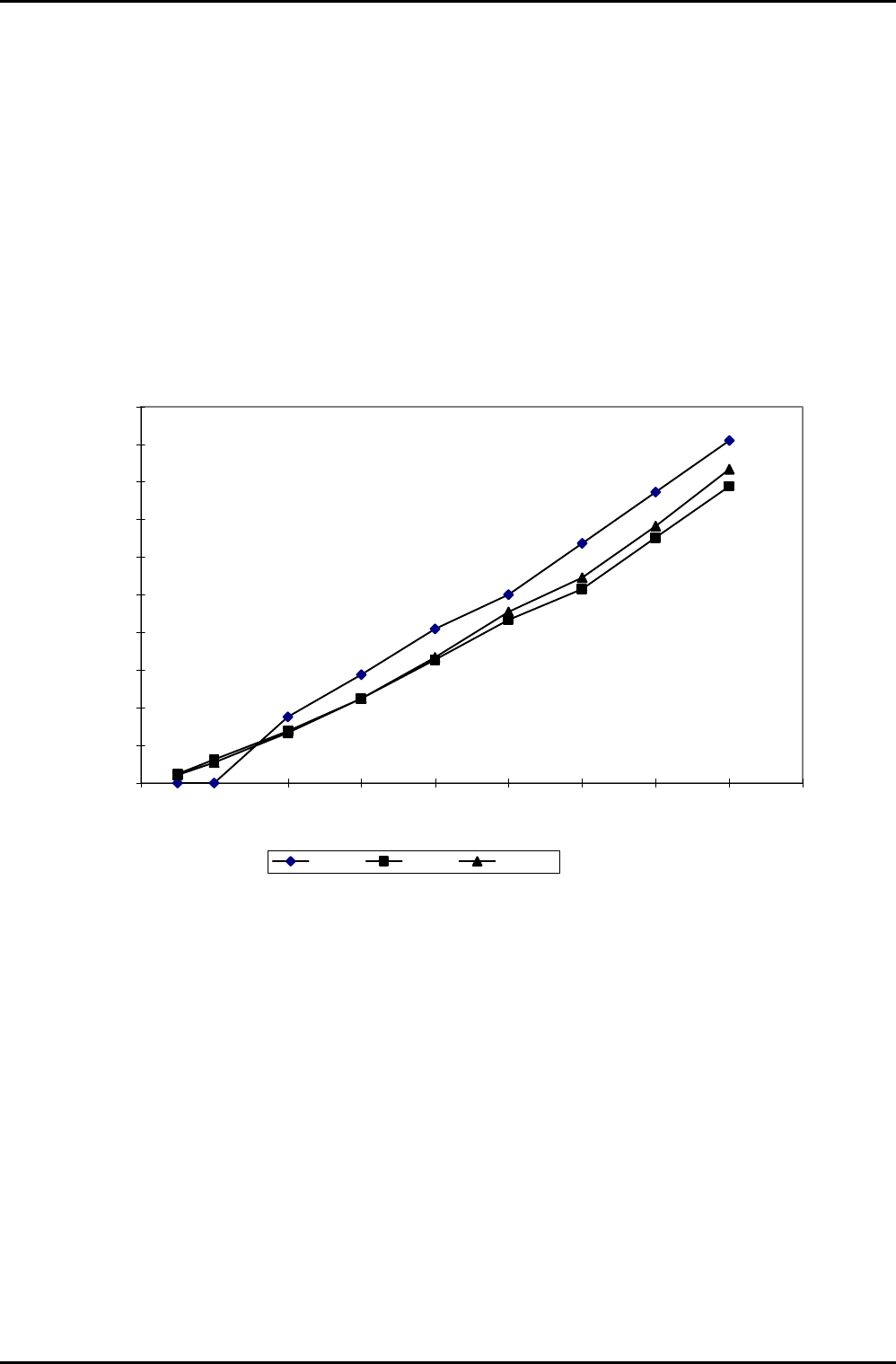
A figure of merit for the ICP is the ion current density at the wafer, without RF applied to the wafer. This
was measured by using the wafer table as an ion collection electrode, biased to -30 V dc. A good figure to
achieve is 1 mA cm-2; much less than this means the source is not effective; much higher currents are not
useful because the sample is heated too much.
The graph (see Fig 3) shows a nearly linear increase of ion current density with ICP power. There is no sign
of saturation behaviour (unlike ECR), so higher powers could be used to get higher ion fluxes if required.
The ICP 180 can handle up to 3 kW of RF power.
0
0.2
0.4
0.6
0.8
1
1.2
1.4
1.6
1.8
2
0 200 400 600 800 1000 1200 1400 1600 1800
ICP W
Ion current density mA/cm2
2 mtorr 7 mtorr 60 mtorr
Fig 3: Ion current density at the wafer versus ICP power
ICP 180 Source
Printed: 18-Jan-06, 8:44 Page 9 of 26 Issue 3 : December 00
mä~ëã~ä~Ä=f`m=NUM lñÑçêÇ=fåëíêìãÉåíë=mä~ëã~=qÉÅÜåçäçÖó== Equipment Manual=
Operating window
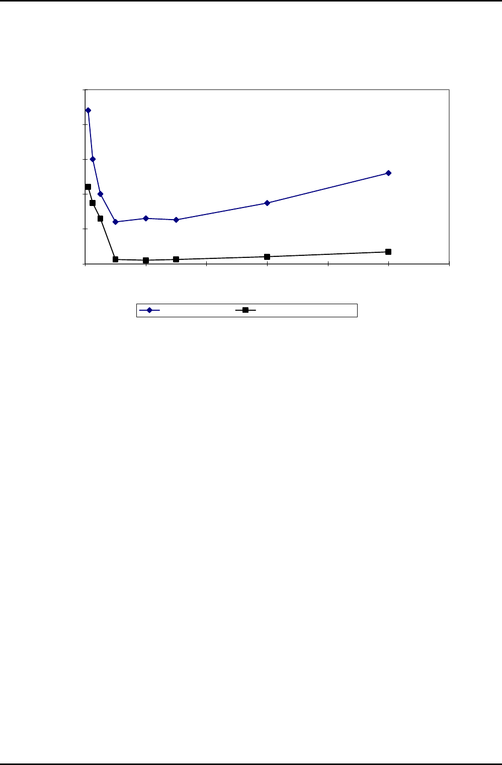
The operating window of the ICP 180 source in nitrogen is shown in Fig 4.
0
500
1000
1500
2000
2500
0 20 40 60 80 100 120
Pressure mtorr
ICP RF power W
ICP strike power W Minimum plasma power W
Fig 4: Operating window
ICP 180 Source
Issue 4: January 06 Page 10 of 26 Printed: 18-Jan-06, 8:44
Equipment Manual lñÑçêÇ=fåëíêìãÉåíë=mä~ëã~=qÉÅÜåçäçÖó== mä~ëã~ä~Ä=f`m=NUM
QK=fåëí~ää~íáçå=
This section applies if the mä~ëã~ä~Ä=f`mNUM=source is supplied as an upgrade, or as an exchangeable
plasma source.
The ICP180 is installed as the entire top lid to a mä~ëã~ä~Ä
=
póëíÉã=NMM, with a vacuum O ring on the
underside of the ICP180 chamber lid. The chamber lid is secured by hinges which enable access to the
process chamber interior for maintenance.
WARNING
PINCH POINT – WHEN THE CHAMBER LID IS OPENED OR CLOSED, LIMBS,
FINGERS ETC CAN BECOME TRAPPED BETWEEN THE LID AND THE PROCESS
CHAMBER BASE RESULTING IN SEVERE INJURY.
Ensure that all personnel are kept clear of the chamber lid when it is
opened or closed.
When opening or closing the chamber lid, ensure that both of your hands
are kept clear of the pinch point.
When the process chamber lid is to be kept in its raised position for
prolonged periods, ensure that it is held safely in its open position
without relying entirely on the gas support struts.
After mechanical mounting, connect the services detailed in Section 2 of this manual.
The RF generator services should be connected according to the manufacturer’s manual supplied with the
generator.
ICP 180 Source
Printed: 18-Jan-06, 8:44 Page 11 of 26 Issue 3 : December 00