Utah-94-721002-System-Manual.pdf - 第81页
System Manual lñÑçêÇ=fåëíêìãÉåíë=mä~ëã~=qÉ ÅÜåçäçÖó== mä~ëã~ä~Ä póëíÉãNMM Continue button: Close the alert dialogue bo x – the alert banner remains displayed on the menu bar. Note that option buttons that are not availab…
mä~ëã~ä~ÄpóëíÉãNMM lñÑçêÇ=fåëíêìãÉåíë=mä~ëã~=qÉÅÜåçäçÖó== System Manual
RKQKP= póëíÉã=~äÉêíë=
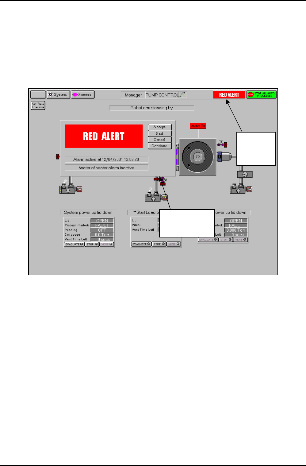
System alerts are displayed when PC 2000 detects an event that requires the attention of the
user. Each alert is automatically categorised depending on the nature of the event and the
response required by the user. The category of the event can range from a warning indicating
that a service parameter is out of tolerance to a process abort indicating that a process
setpoint has been out of tolerance for so long that the process cannot be completed. A
typical system alert is shown in Fig 5.2.
System
A
lert
b
anner
System Alert
dialogue
Fig 5.2: Typical system alert
The alert is displayed as a banner in the menu bar at the top of the screen with an associated
dialogue in the main screen area. Note that more than one alert can be active at the same
time, each requiring action by the user in turn.
There are three categories of alert indicated by the colour and text displayed in the banner
and dialogue:
Blue Warning e.g. water flow low.
Yellow Hazard – not currently used.
Red Process abort, e.g. high-reflected RF power.
A user logged on at any access level can close the alert dialogue, but only a user logged on as
a system manager can clear the alert banner from the menu bar. The dialogue options are:
Accept button: System Managers only. Clear the alert and log it.
Next button: View the next alert.
Cancel button: System Manager only. Clear the alert; do
not log it.
Operating Instructions
UC Davis 94-721001 Issue 1: March 06 Page 5-14 of 52 Printed: 22-Mar-06, 10:42

System Manual lñÑçêÇ=fåëíêìãÉåíë=mä~ëã~=qÉÅÜåçäçÖó== mä~ëã~ä~ÄpóëíÉãNMM
Continue button: Close the alert dialogue box – the alert banner remains displayed
on the menu bar.
Note that option buttons that are not available (i.e. Accept and Cancel due to user ‘logged
on’ status and Next when there is only one active alert) are greyed out.
The alert message usually contains an adequate description of the detected event. If it is a
service fault (water flow, purge gas etc.) then verify that the service is available to the
machine as soon as possible. Depending on the nature of the service, the system may allow
the machine to continue to operate, so that the current process can be completed.
Do not
start a new process before checking the service.
The red alerts are often due to a process setpoint being out of tolerance for too long. In these
cases, the process is halted by the system. If it is authorised to resume processing with a
parameter deviation then:
1) Check the most recent process log to find the process time remaining.
2) Construct a new process with a modified process time and check the ‘Ignore
tolerance’ option. Note that this removes
all tolerance checking. The machine should
be monitored by an operator for further deviations when operated in this condition.
RKQKQ= mìãéáåÖ=Ççïå=
1) On the Pump Control page, select the SET BASE PRESSURE button, then enter the
required process chamber base pressure if different from the default.
2) Ensure that the Automatic load lock/transfer chamber’s lid is closed. (Automatic load
lock/transfer chamber lid open/closed status is shown in the panel adjacent to the
mimic).
3) Click on each dry pump/rotary vane pump mimic to start the pump.
4) Select the Evacuate button for the process chamber. The relevant valves will
operate and the process chamber will be pumped down.
5) Select the Evacuate button for the Automatic load lock. You will be prompted to
enter a wafer identity - either enter the identity and click OK, or click Cancel (to
pump down without a wafer in the Automatic load lock). The relevant valves will
operate and the Automatic load lock will be pumped down.
NOTE: Turning off any rotary vane pump will cause all process and pumping
actions using that pump to stop.
6) To achieve a low base pressure in the system, pump for at least 12 hours. Where
chambers or process heaters are part of the system, raise the temperatures of these
near their maximum values for the first six hours of pumping to assist out-gassing,
then return the temperature to ambient.
WARNING
PARTS OF THE EQUIPMENT MAY BE TOO HOT TO TOUCH DURING CHAMBER
HEATING.
Operating Instructions
Printed: 22-Mar-06, 10:42 Page 5-15 of 52 UC Davis 94-721001 Issue 1: March 06

mä~ëã~ä~ÄpóëíÉãNMM lñÑçêÇ=fåëíêìãÉåíë=mä~ëã~=qÉÅÜåçäçÖó== System Manual
RKQKR= ^ìíçã~íáÅ=éêçÅÉëë=êìå=
An automatic process run as described in this sub-section can be carried out by a user logged
on as a Manager. See sub-section 5.4.6, page 5-17 for details of a single button automatic
process run, which can be carried out by any user.
1) Insert the wafer into the Automatic load lock. (If necessary, vent the Automatic load
lock by selecting the STOP button then the VENT button).
2) Close the Automatic load lock’s lid.
3) Select the relevant EVACUATE button. A dialogue box will be displayed allowing
entry of a Wafer Identity, if any.
4) Check that the system has pumped down to base pressure. (The process chamber
message panel should display ‘Base Pressure reached’.)
5) Ensure that the Automatic load lock is at the required pressure. (Check the relevant
panel on the Pump Control page). Green ‘ready for transfer’ indicators (WX) are
displayed on each chamber mimic when it is available for vacuum transfer.
6) Select the Process menu, then the Recipe option. Click on the Load button then
select the required recipe.
7) Click on the Run button. This will start wafer transfers and wafer processing.
NOTES:
a) You can pause the process at any time by selecting the PAUSE button.
This will cause the Step Time and the plasma power to stop with the
current step time indicated. Re-starting the process will cause the
process to continue from the time it was paused. If, during the pause
period, you change any of the process parameters, e.g. gas demand,
pressure etc., you must press the START button for the changes made to
come into effect, this will cause the step timer to continue from the time
it was paused.
b) You can stop the process at any time; the message ‘Process Complete’
will be displayed, if required, you can then run the same or another
process.
WARNING
CONTACT WITH TOXIC GASES CAN CAUSE DEATH OR SERIOUS INJURY.
WHERE ANY PROCESS GAS IS TOXIC, DO NOT TRANSFER A WAFER FROM THE
PROCESS CHAMBER TO THE LOAD LOCK UNTIL ALL PROCESS GAS HAS BEEN
PUMPED OUT.
ENSURE THAT THE AUTOMATIC VENT SEQUENCE IS ALLOWED TO COMPLETE.
IF THESE PRECAUTIONS ARE NOT CARRIED OUT, THERE COULD BE A HAZARD IN THE
LOAD LOCK.
Operating Instructions
UC Davis 94-721001 Issue 1: March 06 Page 5-16 of 52 Printed: 22-Mar-06, 10:42