Utah-94-721002-System-Manual.pdf - 第139页
System Manual lñÑçêÇ=fåëíêìãÉåíë=mä~ëã~ =qÉÅÜåçäçÖó== mä~ëã~ä~Ä póëíÉãNMM WARNING BEFORE PROCEEDING WITH ANY MAINTENANCE WORK, READ SECTION 1 - HEALTH AND SAFETY . SKNP= ^ÇàìëíáåÖ=íÜÉ=äçïÉê=ÉäÉÅíêçÇ É=ï~ÑÉê=Åä~ãé=Åä~ãéáå…
mä~ëã~ä~ÄpóëíÉãNMM lñÑçêÇ=fåëíêìãÉåíë=mä~ëã~=qÉÅÜåçäçÖó== System Manual
WARNING
BEFORE PROCEEDING WITH ANY MAINTENANCE WORK, READ SECTION 1 - HEALTH AND SAFETY.
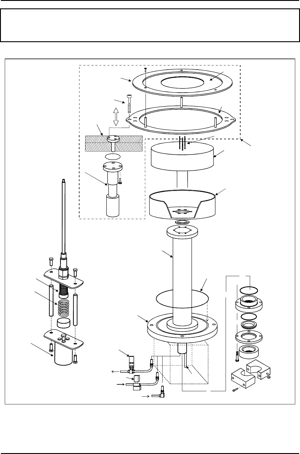
THERMOCOUPLE
CHAMBER
BASE
WAFER
CLAMP
TABLE
DARK SPACE
SHIELD
TABLE SUPPORT
TUBE
O RING
PUMPDOWN
PIPE FLANGE
FEEDTHROUGH
COMPONENTS
STAINLESS
STEEL
BELLOWS
SPRING
COMPRESSED
AIR CYLINDER
COMPRESSED
AIR CYLINDER
(ONE EACH SIDE
OF CLAMPING
PLATE)
WAFER
LIFT
ASSEMBLY
(FITS INSIDE
TABLE SUPPORT
TUBE)
Clamping
plate
Clamping
ring
Setscrew &
compression
spring (3-off
on each side
of clamping
ring)
3-pin wafer
support
Quartz
insert
SAFETY RELIEF
VALVE
CONTROL VALVE
LIQUID NITROGEN
IN
LIQUID NITROGEN
OUT
HELIUM IN
Fig 6.1: 94-100-5-12A Cryo / heated -150 / 400C He lower electrode
Maintenance
UC Davis 94-721001 Issue 1: March 06 Page 6-20 of 22 Printed: 22-Mar-06, 7:41
System Manual lñÑçêÇ=fåëíêìãÉåíë=mä~ëã~=qÉÅÜåçäçÖó== mä~ëã~ä~ÄpóëíÉãNMM
WARNING
BEFORE PROCEEDING WITH ANY MAINTENANCE WORK, READ SECTION 1 - HEALTH AND SAFETY.
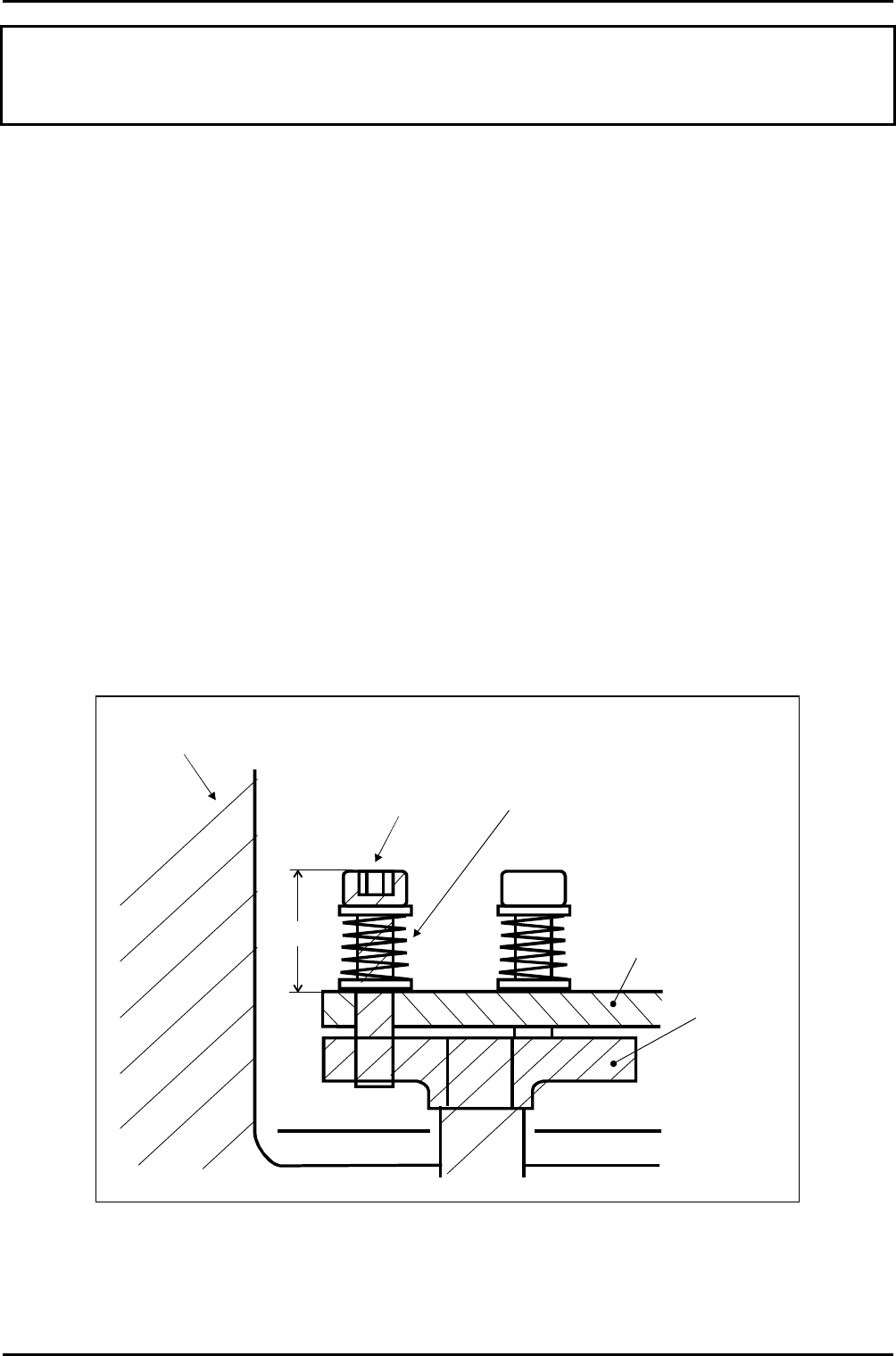
SKNP= ^ÇàìëíáåÖ=íÜÉ=äçïÉê=ÉäÉÅíêçÇÉ=ï~ÑÉê=Åä~ãé=Åä~ãéáåÖ=ÑçêÅÉ=
To adjust the clamping force, use the following procedure (refer to Fig 6.1 and Fig 6.2):
11) Open the process chamber lid.
12) Wearing powder-free gloves, unscrew the three clamping plate securing screws then
remove the clamping plate from the process chamber and place it on a clean surface.
13) Using an M5 socket wrench, rotate the setscrews to adjust the length of compression
springs. Ensure that all six setscrews (i.e. three at each side of the clamping ring) are
rotated sequentially and equally.
NOTE: The nominal distance between the base of the clamping plate and the top
of the head of each setscew is 17mm to give a minimal clamping force. This
distance can be decreased to a minimum of 10mm to increase the clamping
force. Each spring gives a force of 1 Newton per mm compression, so for
example, a 5mm increase in compression (i.e. reducing the distance) on
each spring gives 5 x 6 = 30 Newtons increased clamping force.
Re-fit the clamping plate, reversing Step 2).
Close the process chamber lid.
17mm
Process
chamber
Clamping
ring
M5 x 40 Setscrew
cut overall length
down to 30mm
Compression
spring
G/SUN/SPG/012
Air cylinder
piston
top plate
Fig 6.2: Clamping force adjustment
Maintenance
Printed: 22-Mar-06, 7:41 Page 6-21 of 22 UC Davis 94-721001 Issue 1: March 06
mä~ëã~ä~ÄpóëíÉãNMM lñÑçêÇ=fåëíêìãÉåíë=mä~ëã~=qÉÅÜåçäçÖó== System Manual
WARNING
BEFORE PROCEEDING WITH ANY MAINTENANCE WORK, READ SECTION 1 - HEALTH AND SAFETY.
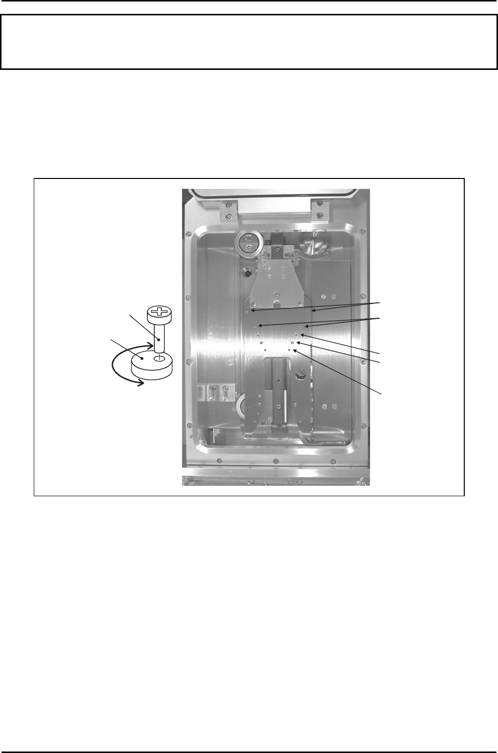
SKNQ= ^ìíçã~íáÅ=äç~Ç=äçÅâ=ÉåÇ=ÉÑÑÉÅíçê=~ÇàìëíãÉåíë=Ñçê=ÇáÑÑÉêÉåí=
ï~ÑÉê=ëáòÉë=
The automatic load lock end effector can accommodate wafer diameters of 3” to 8”. This is
achieved using a series of pairs of holes appropriately spaced for the different wafer sizes
into which concentric cams are secured. See Fig 6.3.
Concentric cam
locations for 8“
wafers
Concentric cam
locations for 6“
wafers
Concentric cam
locations for 4“
wafers (cams shown
in this position)
Location for 5“ wafers
Location for 3“ wafers
Concentric cam
detail
Securing
screw
Cam
Rotating the cam
about the securing
screw provides a
small forwards/
backwards adjustment
of the wafer position.
Fig 6.3: End effector wafer size adjustments
To set up the end effector for a wafer size different to that previously processed, use the
following procedure:
1) If necessary, vent the automatic load lock.
2) Open the automatic load lock’s lid.
3) Wearing powder-free gloves, remove both concentric cams/securing screws from the
end effector, then fit them into the appropriate holes for the wafer size to be
processed. See Fig 6.3.
4) Close the automatic load lock’s lid, then carry out a test wafer load into a process
chamber. Ensure that the wafer is located centrally on the lower electrode. If
necessary, rotate the concentric cams until the wafer is located centrally.
Maintenance
UC Davis 94-721001 Issue 1: March 06 Page 6-22 of 22 Printed: 22-Mar-06, 7:41