Utah-94-721002-System-Manual.pdf - 第109页
System Manual lñÑçêÇ=fåëíêìãÉåíë=mä~ëã~=qÉ ÅÜåçäçÖó== mä~ëã~ä~Ä póëíÉãNMM The low pressure strike feature allows plasma proc essing at low pressures. When the gas pressu re is too low, it is not possible to strike a plas…
mä~ëã~ä~ÄpóëíÉãNMM lñÑçêÇ=fåëíêìãÉåíë=mä~ëã~=qÉÅÜåçäçÖó== System Manual
RF Generator
panel
Enter the required forward power. The forward power, reflected
power, power ON/OFF status and DC bias are displayed.
Clicking the Set Fwd Power button toggles the demand between a
forward power set point and a DC bias set point. If a DC bias demand
is set, the RF power will be varied to try to achieve the required bias.
Use this facility with care: if the plasma does not strike or if the DC
bias cannot be read (by covering the table with insulator), then the RF
power will increase to maximum.
ICP
GENERATOR
panel
Enter the required forward power. The forward power, reflected
power, ON/OFF status are displayed.
CRYO panel
Enter the required table temperature. The current table temperature
is displayed.
HELIUM
BACKING panel
Enter the required backing pressure. The current pressure (Torr) and
flow rate (sccm) are displayed. The open/closed status of the control
valve is displayed.
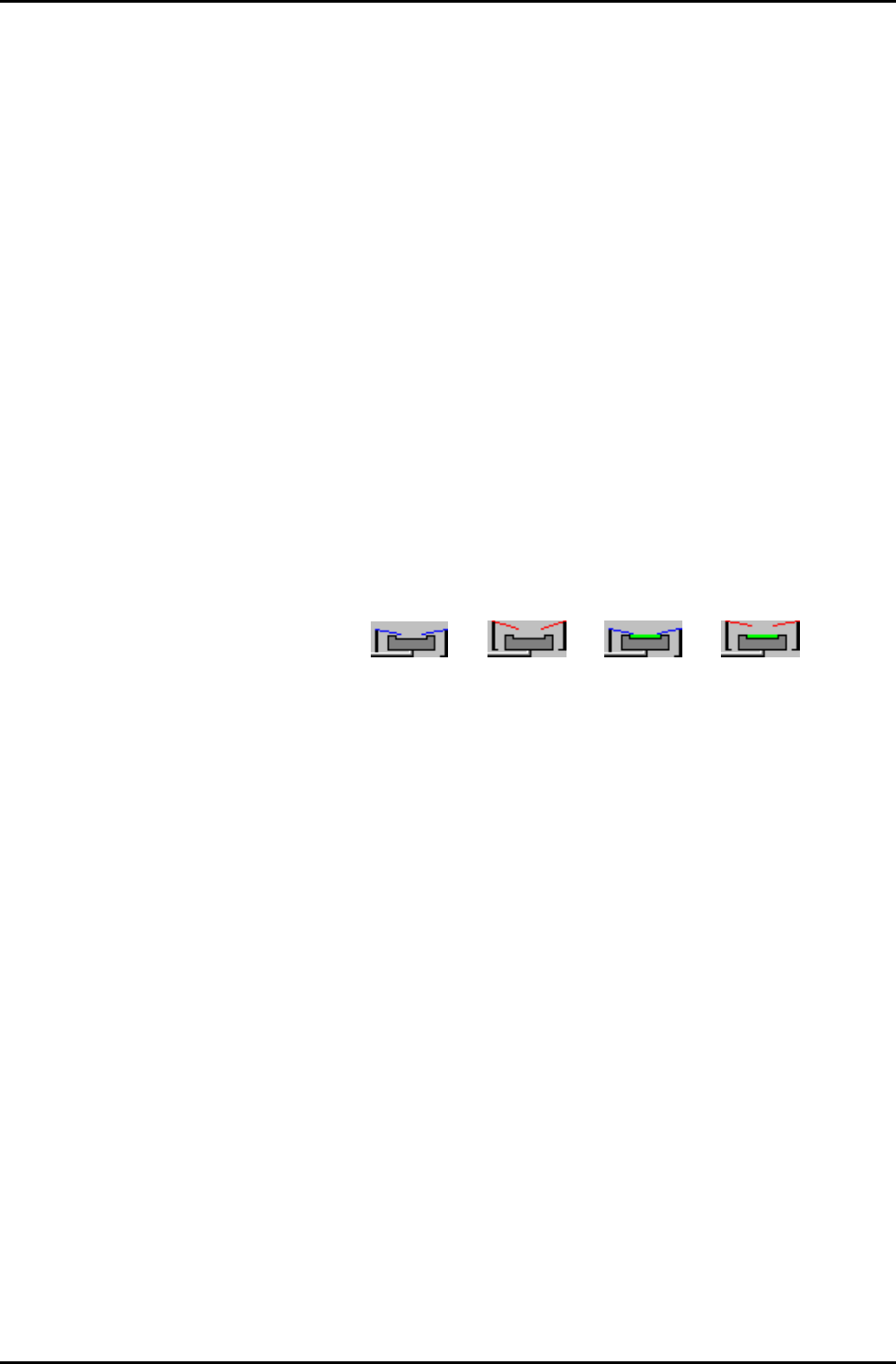
The table mimic, at the top of the panel, displays the up/down status
of the wafer clamp and whether a wafer is loaded or not. The bitmaps
below show all possible states of the mimic.
Clamp down
(no wafer)
Clamp down
(wafer loaded)
Clamp up
(no wafer)
Clamp up
(wafer loaded)
APC
CONTROLLER
panel
Select either the Pressure or the Position button. Enter the required
Chamber Pressure or APC valve position. The current Process Chamber
pressure, Valve Position and valve status are displayed.
Operating Instructions
UC Davis 94-721001 Issue 1: March 06 Page 5-42 of 52 Printed: 22-Mar-06, 10:42

System Manual lñÑçêÇ=fåëíêìãÉåíë=mä~ëã~=qÉÅÜåçäçÖó== mä~ëã~ä~ÄpóëíÉãNMM
The low pressure strike feature allows plasma processing at low
pressures. When the gas pressure is too low, it is not possible to strike
a plasma; however it is possible to sustain a plasma to very low
pressures once it has been ignited. This software feature enables the
user to raise the pressure temporarily, strike a plasma, and
automatically reduce the pressure to the desired value for processing.
The three data fields and their effects are:
LOW PRESSURE
STRIKE panel
Strike
Pressure field
DC bias
Minimum
field
Ramp Rate
field
Enter the value in mTorr at which the RF should
turn on and strike the plasma. If a zero is entered,
the feature is disabled and the RF will turn on once
the pressure has stabilised at the requested process
pressure.
Enter a positive number for the minimum DC bias
value expected once the plasma has struck. Enter
zero if DC bias cannot be read because the
substrate (and any wafer clamp) completely cover
the electrode, or if the electrode has an insulating
coating. A non-zero value is used by the software
to detect if the plasma has been properly
established. If a zero is entered, then the software
assumes the plasma has struck once the RF
reflected power goes low.
Enter a number to set the rate at which the
pressure is reduced from the strike value to the set
point. The higher the number entered, the faster
the transition to process conditions will be. Note
that too high a value can cause the plasma to go
out if the plasma impedance changes faster than
the RF matching unit can track.
Operating Instructions
Printed: 22-Mar-06, 10:42 Page 5-43 of 52 UC Davis 94-721001 Issue 1: March 06
mä~ëã~ä~ÄpóëíÉãNMM lñÑçêÇ=fåëíêìãÉåíë=mä~ëã~=qÉÅÜåçäçÖó== System Manual
Process gas pod
mimic
Displays a mimic of the gas lines installed in the gas pod.
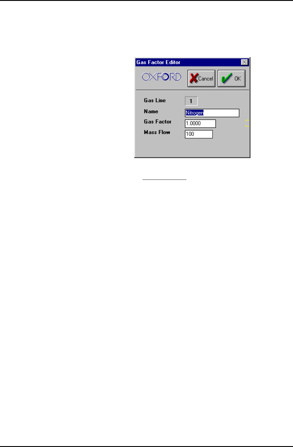
Enter the required gas flow in sccm for each gas line. Click on the Gas
Name in an MFC mimic to edit the associated Gas Factors; the
following dialogue is displayed.
It is recommended to keep the Gas Factor as 1, and to put the full
scale of the MFC
for the gas used in the Mass Flow field.
For example, if Argon is used with a 100 sccm N
2
MFC. Put gas factor 1
and Mass Flow 141 sccm.
Operating Instructions
UC Davis 94-721001 Issue 1: March 06 Page 5-44 of 52 Printed: 22-Mar-06, 10:42