Utah-94-721002-System-Manual.pdf - 第53页
System Manual lñÑçêÇ=få ëíêìãÉåíë=mä~ëã~=qÉÅÜåçäçÖó== mä~ëã~ä~ Ä póëíÉã=NMM PKVKP= VQJUNJVJON=pí~åÇ~êÇ=íçñáÅ=Ö~ë=äáåÉ= The standard toxic gas line is shown in Fig 3.7. All gas fittings are VCR and all stainless steel pip…
mä~ëã~ä~Ä póëíÉã=NMM lñÑçêÇ=fåëíêìãÉåíë=mä~ëã~=qÉÅÜåçäçÖó== System Manual
WARNING
THE CONNECTION FROM THE GAS POD MANIFOLD TO THE PROCESS CHAMBER
SHOULD NOT INCLUDE ANY SHUT OFF VALVE, UNLESS THIS HAS BEEN CLEARED
WITH OXFORD PLASMA TECHNOLOGY. A BLOCKAGE HERE COULD CAUSE PROCESS
GASES TO MIX AND CROSS CONTAMINATE IN THE HIGH PRESSURE GAS DELIVERY
PIPEWORK.
PKVKO= VQJUNJVJNN=pí~åÇ~êÇ=åçåJíçñáÅ=Ö~ë=äáåÉ=
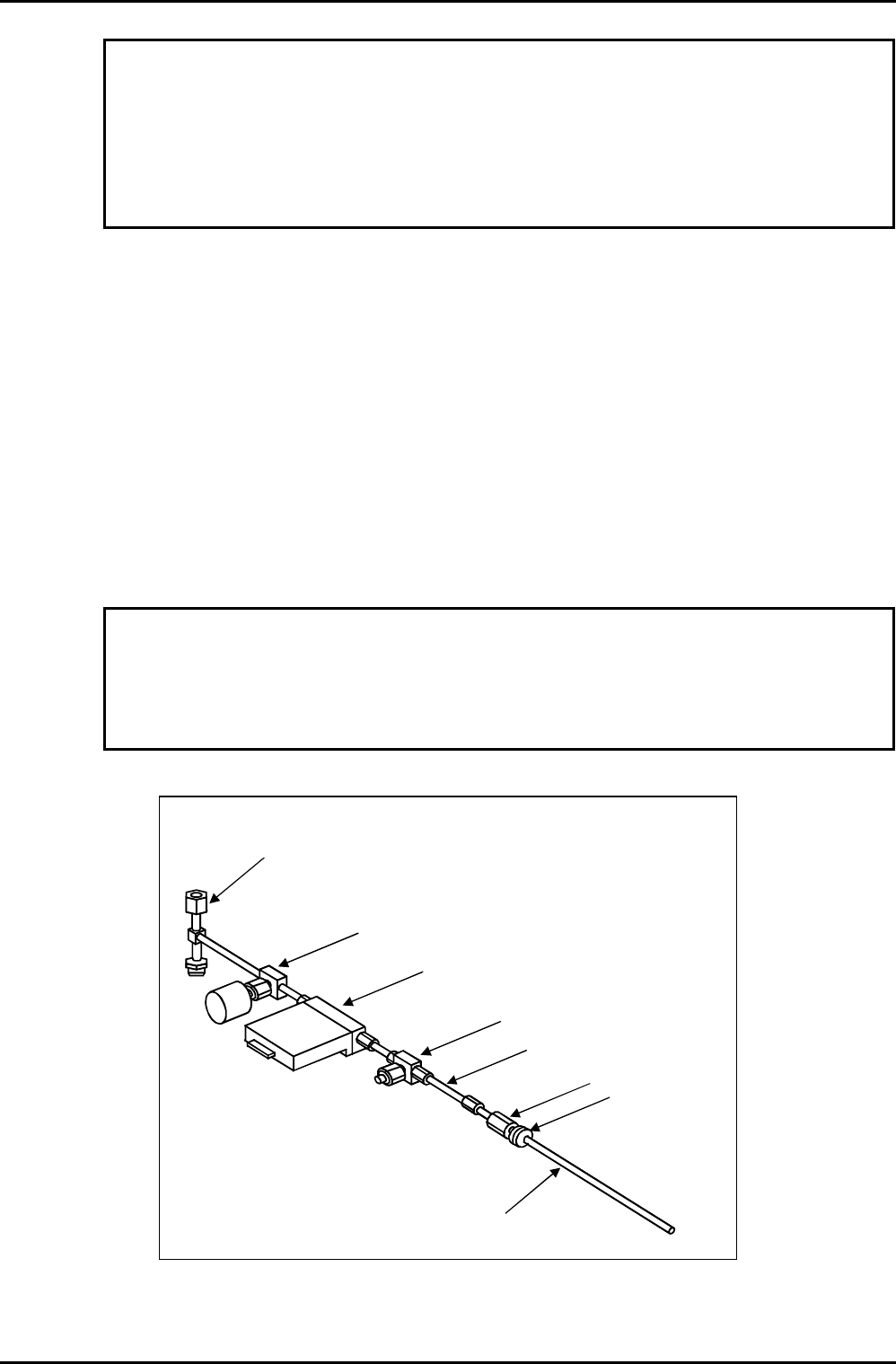
The standard non-toxic gas line is shown in Fig 3.6. All gas fittings are VCR and all stainless
steel pipework connections are welded. The ‘gas in’ tube passes into the side of the case,
protected by a grommet. A ferrite core, fitted to the ‘gas in’ tube, reduces the susceptibility
of the gas pod electronics to signals from nearby transmitting devices, e.g. mobile phones,
modems, etc..
Gas from the customer’s cylinder/regulator/filter flows into the gas in tube to the filter.
The gas flows through the 2-µm filter to the mass flow controller (MFC). The MFC controls the
flow of gas as commanded by the system controller. The gas then flows through the
pneumatically controlled outlet shut-off valve and into the gas out manifold where it is mixed
with the other process gases before flowing into the process chamber.
WARNING
THE CLOSED INLET VALVE REMAINS SHUT FOR DIFFERENTIAL PRESSURE UP TO 5
BAR. A FAILURE UPSTREAM WHICH PRODUCES LINE PRESSURES ABOVE THIS WILL
NOT BE CONTAINED. IF THIS PRODUCES A HAZARD, THE CUSTOMER IS WARNED TO
FIT ADDITIONAL PROTECTION UPSTREAM.
GAS IN TUBE
(STAINLESS STEEL)
GROMMET
2 µm FILTER
GAS LINE EXTENSION
FERRITE CORE
MASS
FLOW
CONTROLLER
GAS OUT
MANIFOLD
OUTLET SHUT-OFF
VALVE
(PNEUMATICALLY
CONTROLLED)
Fig 3.6: 94-81-9-11 Standard non-toxic gas lines
Description
UC Davis 94-721001 Issue 1: March 06 Page 3-16 of 22 Printed: 22-Mar-06, 7:29
System Manual lñÑçêÇ=fåëíêìãÉåíë=mä~ëã~=qÉÅÜåçäçÖó== mä~ëã~ä~Ä póëíÉã=NMM
PKVKP= VQJUNJVJON=pí~åÇ~êÇ=íçñáÅ=Ö~ë=äáåÉ=
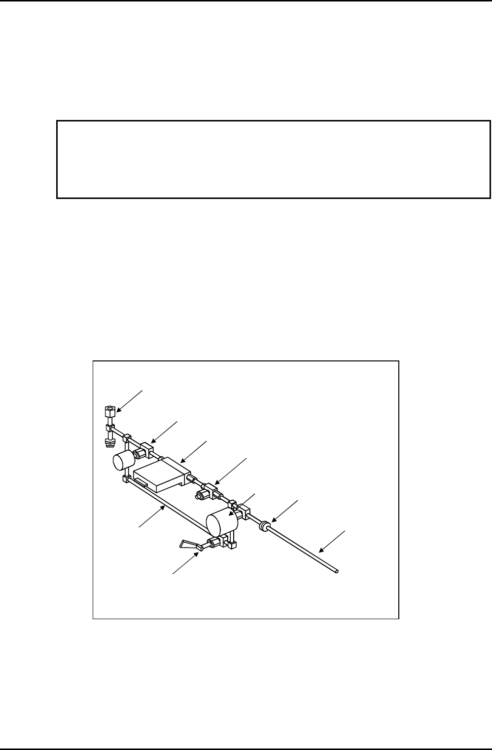
The standard toxic gas line is shown in Fig 3.7. All gas fittings are VCR and all stainless steel
pipework connections are welded. The gas in tube passes into the side of the gas pod case,
protected by a grommet.
Gas from the customer’s cylinder/regulator/filter flows into the gas in tube to the filter.
WARNING
THE CLOSED INLET VALVE REMAINS SHUT FOR DIFFERENTIAL PRESSURE UP TO 210
BAR. A FAILURE UPSTREAM WHICH PRODUCES LINE PRESSURES ABOVE THIS WILL
NOT BE CONTAINED. IF THIS PRODUCES A HAZARD, THE CUSTOMER IS WARNED TO
FIT ADDITIONAL PROTECTION UPSTREAM.
With the Inlet Valve and Outlet Valve open and the Bypass Valve closed, the gas flows
through the 2 µm filter to the mass flow controller (MFC). The MFC controls the flow of gas as
commanded by the system controller. The gas then flows through the outlet valve and into
the gas out manifold where it is mixed with the other process gases before flowing into the
process chamber.
With the Bypass Valve open, the gas flows through the bypass line directly to the gas out
manifold. This facility is provided to enable the toxic gas line to be evacuated by pumping
down the process chamber. This is necessary to prevent air entering the gas line and
contaminating it during a gas cylinder changeover, and to service the gas line in the event of
an MFC or filter blockage.
GAS IN TUBE
(STAINLESS STEEL)
GROMMET
INLET VALVE
(PNEUMATICALLY
CONTROLLED
SHUT-OFF)
OUTLET VALVE
(PNEUMATICALLY
CONTROLLED
SHUT-OFF)
2 µm FILTER
BYPASS VALVE
(MANUALLY
OPERATED
SHUT-OFF)
MASS
FLOW
CONTROLLER
GAS OUT
MANIFOLD
BYPASS
LINE
Fig 3.7: 94-81-9-21 Standard toxic gas line
PKVKQ= VQJUNJVJMMLQ=d~ë=äáåÉ=áåíÉêäçÅâ=âáí=
The gas line interlock kit is a pneumatically controlled hardware interlock, which prevents the
simultaneous flow of process gases, which if combined could produce a hazardous mixture.
Description
Printed: 22-Mar-06, 7:29 Page 3-17 of 22 UC Davis 94-721001 Issue 1: March 06
mä~ëã~ä~Ä póëíÉã=NMM lñÑçêÇ=fåëíêìãÉåíë=mä~ëã~=qÉÅÜåçäçÖó== System Manual
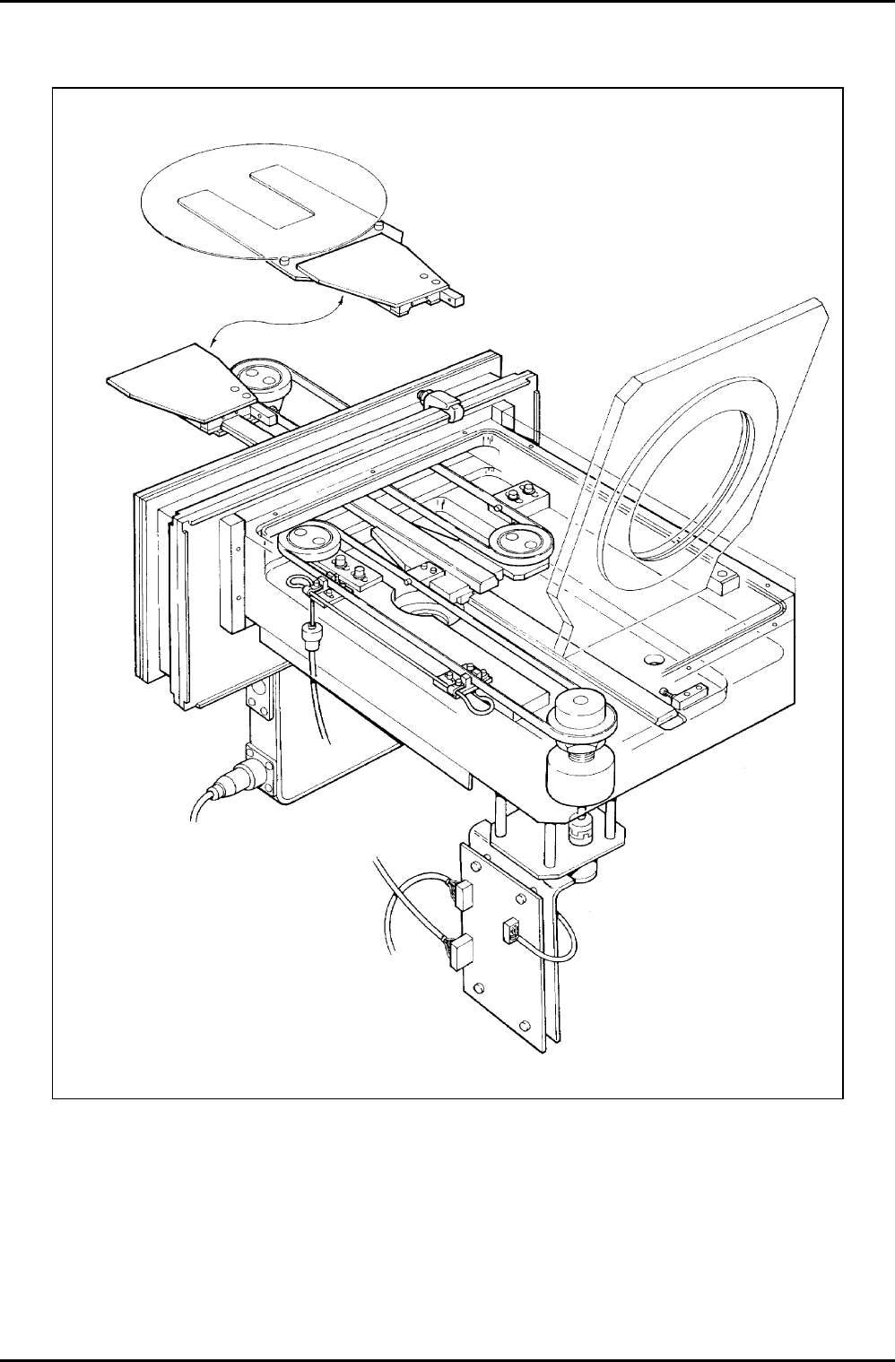
PKNM= VQJNMMJNMJMR`=páåÖäÉ=ï~ÑÉê=~ìíçã~íáÅ=äç~Ç=äçÅâ==
Fig 3.8: Single wafer automatic load lock
Description
UC Davis 94-721001 Issue 1: March 06 Page 3-18 of 22 Printed: 22-Mar-06, 7:29