CP643E.pdf - 第101页
FK-9F98-05 CP-643E Training Text for Service Engineers Edition 5.0 Chapter 6. Servo Pack Zero Setting and Gain/ Motion Check [ 10 / 14] Fuji Machine Mfg. Co., Ltd. Okazaki SMT Equipment Quality As surance Dept. Technical…

FK-9F98-05 CP-643E Training Text for Service Engineers
Edition 5.0 Chapter 6. Servo Pack Zero Setting and Gain/ Motion Check [9/14]
Fuji Machine Mfg. Co., Ltd. Okazaki
SMT Equipment Quality Assurance Dept.
Technical Support Div. Section No.2
6
-
9
FQ ad FRQ axis REV (Reverse)
st_pos 0 speed 100000 kps 120
en_pos 400 Reach 8 kis 1
time 35 Rough 10 kpm 160
pitch 0 Accel 15 kim 0
z_high 100 Reduce 15 kff 30
z_creep 50 s_par 0 kaa 0
z_reduce 500 Lim_pe 0 kpi 165
Cam_sp1 0 limit 0 kii/128 500
Cam_sp2 0 h_speed 100 cam_pos1 0
Cycle 0 deflect 10000 cam_pos2 0
Da_sign 0 t_out 10000 sign 0
***** 00000 ***** 00000 pulse 0
NC-axis REV (Reverse)
st_pos 0 speed 45000 kps 80
en_pos 300 reach 10 kis 1
time 35 rough 20 kpm 170
pitch 0 accel 30 kim 0
z_high 50 Reduce 30 kff 70
z_creep 10 s_par 10 kaa 0
z_reduce 100 lim_pe 0 kpi 120
cam_sp1 0 limit 0 kii/128 0
cam_sp2 0 h_speed 100 cam_pos1 0
cycle 0 deflect 10000 cam_pos2 0
da_sign 0 t_out 10000 sign 0
***** 00000 ***** 00000 pulse 0
Change the bold values for reverse operation.
FK-9F98-05 CP-643E Training Text for Service Engineers
Edition 5.0 Chapter 6. Servo Pack Zero Setting and Gain/ Motion Check [10/14]
Fuji Machine Mfg. Co., Ltd. Okazaki
SMT Equipment Quality Assurance Dept.
Technical Support Div. Section No.2
6
-
10
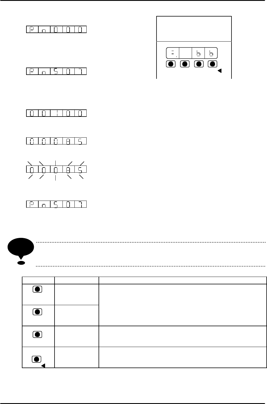
Basic Operation for the Panel Operator
1. Press the MODE/SET key to select the setting.
2. Press the UP or DOWN key to select the desired
number.
e.g.) Select Pn507.
3. Press the DATA/SHIFT key for more than 1 second. The present data will be
displayed.
?00100?
4. Press the Up or DOWN key to change to the desired data,?00085?.
Keeping on pressing and the display will change faster.
5. Press the DATA/SHIFT key more than 1 second. The data will blink and be memorized.
6. Press the DATA/SHIFT key more than 1 second again. The display will return to what it
used to be.
This is how to change Pn507’s from 100 to 85. If it is necessary to change the data
again, repeat the operation in items 2 to 6.
In case of adding a digit, move to the left and press the DATA/SHIFT key
(within 1 second.)
Key Name Function
UP Key
DOWN Key
? Press to display user setting or value.
¤ Press UP key to increase the value.
¤ Press DOWN key to decrease the value.
? It is possible to reset the servo alarm by pressing the UP
and DOWN keys at the same time.
MODE/SET
Key
? Press to change among state display mode,
supplementary function mode, setting mode or monitor
mode.
DATA/SHIFT
Key
? Press to display user setting or value.
? To change the digit for the setting mode, to use as a data-
set key.
NOTE
MODE/S ? ?
DATA/
YASSUKA
SERVOPAC
SSGDM-
200
?
DATA/
MODE/S
?

FK-9F98-05 CP-643E Training Text for Service Engineers
Edition 5.0 Chapter 6. Servo Pack Zero Setting and Gain/ Motion Check [11/14]
Fuji Machine Mfg. Co., Ltd. Okazaki
SMT Equipment Quality Assurance Dept.
Technical Support Div. Section No.2
6
-
11
CP643ME Servo Adjustment Procedure
Mechanical check software, servo adjustment software, is used to adjust the servo system on the
CP643ME. The following is the servo adjustment instruction using the software. This instruction is
supported by servo ROM 305 or after.
1 Boot the mechanical check software.
3 ( Axis change-SW)+ RESET + POWER ON
2 Set each cam lever stopper as follows by I/O.
I/O (F3)? Standard I/O(F1)? OUT (F2)? Use +PAGE ,–PAGE , or ? , ? to set the
cursor. ? ON/OFF (F5)
Y014 SHUTTER1 UP ? Y028 PLACE SOL ON ×
Y015 SHUTTER1 DOWN × Y029 PLACE SOL OFF ?
Y016 SHUTTER2 UP ? Y02A NOZ SOL ON ×
Y017 SHUTTER2 DOWN × Y02B NOZ SOL OFF ?
Y020 PICKUP SOL ON × Y02C PRQ ROT.SOL ON ×
Y021 PICKUP SOL OFF ? Y02D PRQ ROT.SOL OFF ?
Y022 PQ ROT SOL ON × Y02E PRQ ROT 90DEG ×
Y023 PQ ROT SOL OFF ? Y02F PRQ ROT 270DEG ?
Y024 PQ ROT 90DEG ? Y030 FQ SOL ON ×
Y025 PQ ROT 270DEG × Y031 FQ SOL OFF ?
Y026 TAPE FEED SOL ON ×
Y027 TAPE FEED SOL OFF ?
Set the cam angle to 0 degrees when operating I/O.
3 Select the axis to be adjusted.
SERVO (F5) ? +PAGE , -PAGE
4 Select the servo activating mode.
SERVO MOVE (F1)
5 Zero set.
MOVE MODE (F4)? Select “zero set mode”.
(“zero set mode” and “test move mode” switches alternately.) SERVO ON (F1)? START
6 Zero adjust the servo.
? Automatic Adjustment
Press an emergency button.
MODE/ SET ? F n 0 0 0 ? ? ? F n 0 0 9
? Press DATA/SHIFT more than 1 second. ? r E F - 0 ? MODE/ SET
? d o n E (1 second blinks), then press r E F - 0 ? DATA/SHIFT more than 1 second.
? F n 0 0 9 ? Finish.