CP643E.pdf - 第106页
FK-9F98- 05 CP- 643E Training Text for Service Engineers Edition 5.0 Chapter 7. Camera Adjustment [ 1 / 10] Fuji Machine Mfg. Co., Ltd. Okazaki SMT Equipment Quality Assurance Dept. Technical Support Div. Section No.2 7-…

FK-9F98-05 CP-643E Training Text for Service Engineers
Edition 5.0 Chapter 6. Servo Pack Zero Setting and Gain/ Motion Check [14/14]
Fuji Machine Mfg. Co., Ltd. Okazaki
SMT Equipment Quality Assurance Dept.
Technical Support Div. Section No.2
6
-
14
Notes:
FK-9F98-05 CP-643E Training Text for Service Engineers
Edition 5.0 Chapter 7. Camera Adjustment [1/10]
Fuji Machine Mfg. Co., Ltd. Okazaki
SMT Equipment Quality Assurance Dept.
Technical Support Div. Section No.2
7-1
Chapter 7 Camera Adjustment
Parts Cameras
Two CCD cameras are mounted on the machine for inspection of the parts picked at the first station.
The raw image is captured by the cameras and compared with part data to ensure that the part’s
dimensions are within specified tolerances.
Problems that arise from an incorrectly adjusted camera include displaced parts, high error rates, and
skewed parts. Some other examples of possible reasons for re-calibration are:
• Lens replacement
• Camera replacement
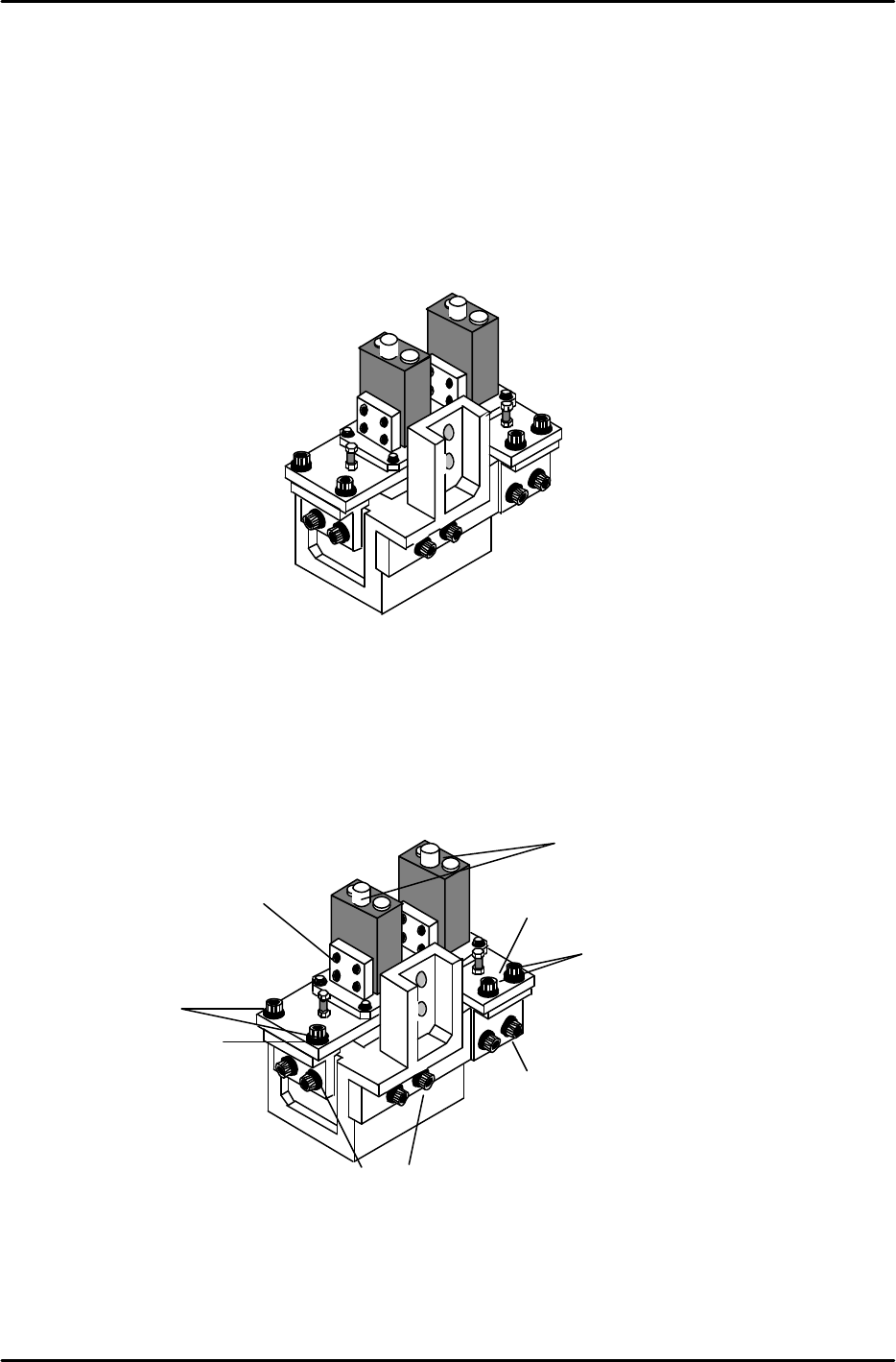
7.1 Parts Camera removal
1. With the machine power OFF, remove the video cables from the cameras.
2. Remove the mounting bolts indicated in Fig. 2 and carefully remove the cameras.
Rear View
Camera3
Camera 2
Narrow Camera
Wide Camera
Figure 1
Rear View
Video Cables
Loosen these two
bolts to remove the
Narrow camera
Loosen these two
bolts to remove the
Wide camera
Figure 2
13N.m
13N.m
8N.m
1.5N.m
8N.m
FK-9F98-05 CP-643E Training Text for Service Engineers
Edition 5.0 Chapter 7. Camera Adjustment [2/10]
Fuji Machine Mfg. Co., Ltd. Okazaki
SMT Equipment Quality Assurance Dept.
Technical Support Div. Section No.2
7-2
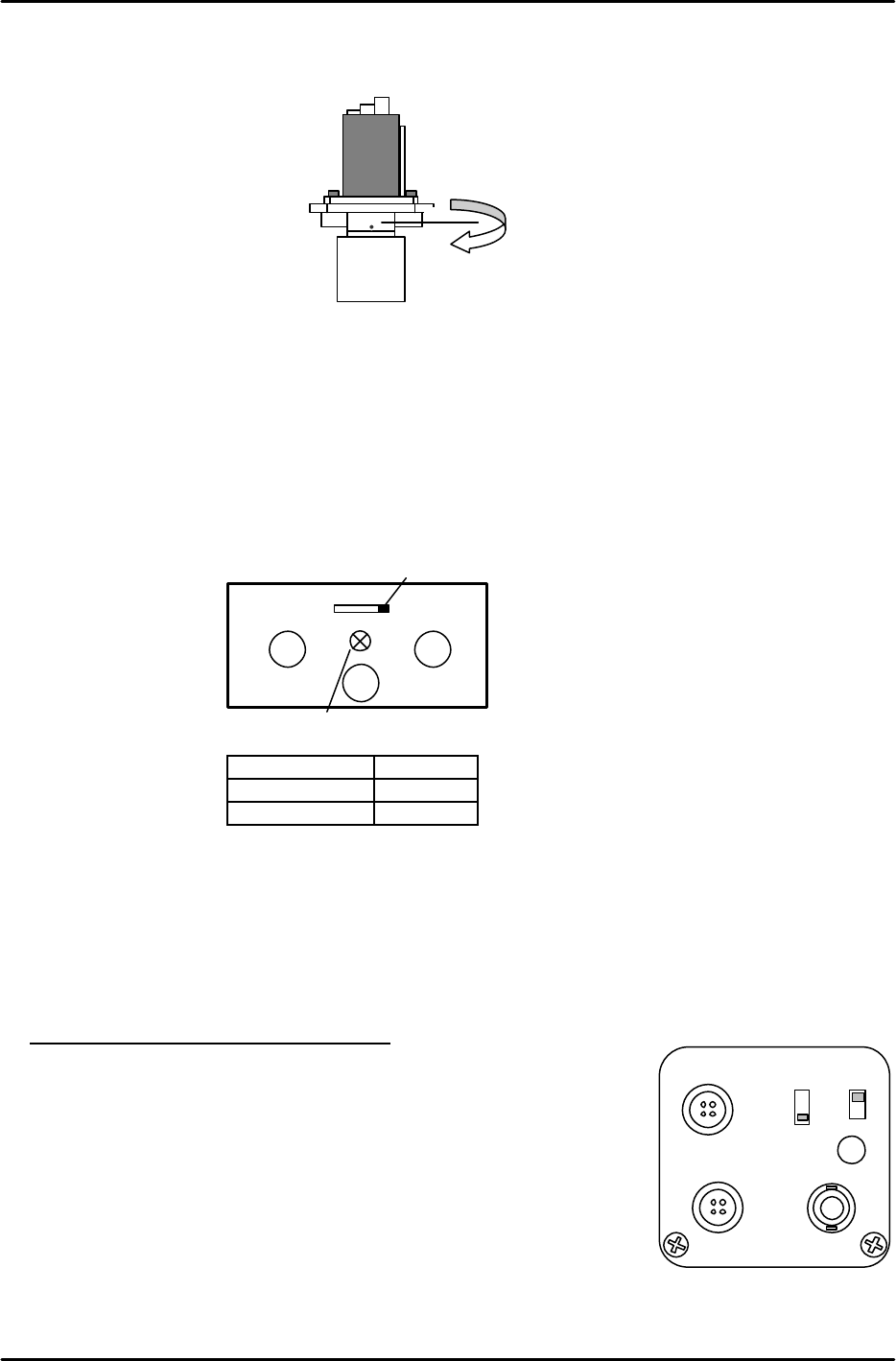
3. Remove the lens assembly by unscrewing it from the CCD module (see figure 3).
7.2 Camera Settings
1. Make the following amplifier and aperture settings prior to returning the cameras to the machine.
These settings are for the standard Wide and Narrow cameras.
Camera Aperture
Wide 4
Narrow 2
2. Where applicable, install the lens assembly to the new CCD module, and then remount the camera
and lens unit to the camera bracket.
3. Install the cameras in the machine.
4. Ensuring that the power supply to the machine is OFF, reconnect the video cables to the cameras.
5. Settings for 0603 Optional Narrow camera:
a. Adjust the set-up of the switch positioned behind the camera.
SELECT switch : 1/30I
GAIN switch : ON
SHUTTER switch : E
Aperture : 2 (Fully open)
b. Set the proper to support 0603.
Machine ID xxxx xxxx xxxx xx1x (x =0 or 1)
Standard narrow camera = 0 0603 camera = 1
c. For the focus, set the 0603 calibration jig. Temporarily adjust the camera height so that the
edge will be clearly seen by the front camera. Focus should be good with 1005R parts.
Manual gain adj. trimmer
GAIN switch
GAIN
A
F
M
LENS
DCIN/SYWC
VIDEO OUT
Top view
Figure 4
DC IN12V
VIDEO
SHUTTER
GAIN
DC IN/SYNC
SELECT
1/30N
1/60N
1/30I
ON
OFF
Figure 5
Figure 3