CP643E.pdf - 第94页
FK-9F98-05 CP-643E Training Text for Service Engineers Edition 5.0 Chapter 6. Servo Pack Zero Setting and Gain/ Motion Check [ 3 / 14] Fuji Machine Mfg. Co., Ltd. Okazaki SMT Equipment Quality As surance Dept. Technical …
FK-9F98-05 CP-643E Training Text for Service Engineers
Edition 5.0 Chapter 6. Servo Pack Zero Setting and Gain/ Motion Check [2/14]
Fuji Machine Mfg. Co., Ltd. Okazaki
SMT Equipment Quality Assurance Dept.
Technical Support Div. Section No.2
6
-
2
6.3 D-axis Servo Pack Zero Adjustment
1. In mechachek mode, press [V_TEST] (F3) → [ZERO] (F3) → [START]
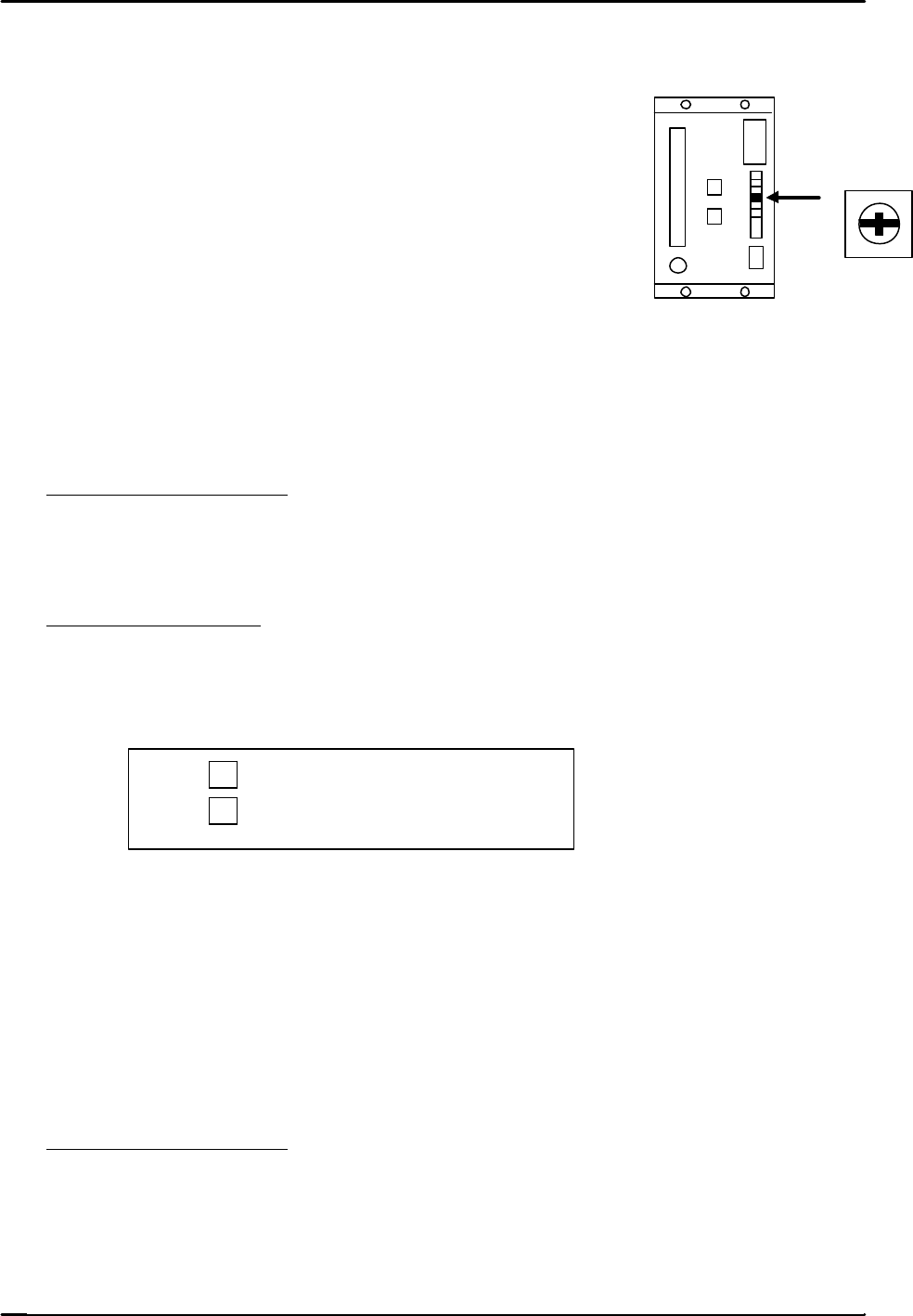
2. Adjust the “ZERO” volume pot on the servo amplifier to
stabilize the counter value.
3. Press the E–stop after the counter value becomes stable.
6.4 C and X Axis Servo Pack Zero Adjustment
1. Connect a digital operator to the servo amplifier.
2. In mechachek mode, press [V_TEST] (F3) → [ZERO] (F3) → [START]
3. The servo counter value appears on the screen and the value changes.
4. Zero adjust automatically and then manually.
Automatic Zero Adjustment
On the digital operator, press [DSPL SET] → [CN – 00] → [DATA ENTER] → [00-00]
→ [press the up arrow to display 00-01] → [DSPL SET] The flashing display will pause for
a second then begin flashing again.
Manual Zero Adjustment
On the digital operator, [press the up arrow to display 00-03] →[DSPL SET] → Press once
to [A_ ###] → [Press the up/down arrow keys on the digital operator in order to stabilize
the counter value.
? … Offset toward positive.
? … Offset toward negative.
When the value stabilizes, press → [DSPL SET] and the data will be memorized.
Press [CYCLE STOP] to stop the adjustment ? [DATA ENTER] ? [CN-00]
6.5 FQ, FRQ, NC, Y, and Z axis Servo Pack Zero Adjustment
1. Adjust using the keys on the face of the servo pack.
2. Perform Automatic and then Manual zero adjustments.
Automatic Zero Adjustment
1. Press an emergency button.
2. Press [MODE / SET] ? [FN 000] ? [Up arrow] ? [FN 009] ? [DATA/SHIFT] (for more
than one second) ? [REF – 0] ? [MODE SET] ? [done] (blinks for one second) ? then
press, [REF – 0] ? [DATA SHIFT] (for more than 1 second) ? [FN 009].
ZERO
FK-9F98-05 CP-643E Training Text for Service Engineers
Edition 5.0 Chapter 6. Servo Pack Zero Setting and Gain/ Motion Check [3/14]
Fuji Machine Mfg. Co., Ltd. Okazaki
SMT Equipment Quality Assurance Dept.
Technical Support Div. Section No.2
6
-
3
Manual Zero Adjustment
1. Release the E-Stop to apply servo power.
2. Press [V_TEST] (F3) → [ZERO] (F3) → [START]
3. The servo counter value will display on the monitor and the value changes.
4. Press [MODE / SET] ? [FN 000] ? [Up arrow] ? [FN 00A] ? [DATA/SHIFT] (for more than one
second) ? [S. PD] ? [DATA/SHIFT] ? [####]? [Press the up/down arrow keys on the face of the
servo pack in order to stabilize the counter value.
? … Offset toward positive.
? … Offset toward negative.
5. After the counter value becomes stable, press [DATA/SHIFT] ? [S. PD] ? [DATA/SHIFT]
(for more than 1 second and the data will be memorized.)
6. Press the Emergency Stop ? [DATA/SHIFT] ? [FN 00A]
7. Procedure complete
6.6 D-axis Gain / Motion Check
1. When adjusting the gain and motion of the D-axis, do so with NO feeders attached to the tables.
2. Select the D-axis ? [SERVO MOVE] ? [SERVO ON] ? [START] to zero set.
3. Press ? [MOVE MODE] ? “Test move mode” ? [MODE] ? [GAIN TEST ] ? [START]
The following items will be displayed on the monitor:
* Movement time in milliseconds.
* Maximum over shoot amount in pulses.
4. Check that the movement time and overshoot are within the ranges specified in chart 1. (page 6-5)
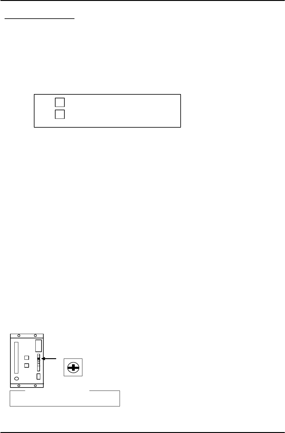
5. Slowly turn the “LOOP” pot on the D- axis servo amplifier so that both values are within tolerance.
L O O P
? Reference?
D-axis : 7.5 scale

FK-9F98-05 CP-643E Training Text for Service Engineers
Edition 5.0 Chapter 6. Servo Pack Zero Setting and Gain/ Motion Check [4/14]
Fuji Machine Mfg. Co., Ltd. Okazaki
SMT Equipment Quality Assurance Dept.
Technical Support Div. Section No.2
6
-
4
6.7 C and X axes Gain / Motion Check
1. Using the digital operator, ensure the servo pack parameters match the parameter table.
2. Select the axis ? [SERVO MOVE] ? [SERVO ON] ? [START] to zero set.
3. Press ? [MOVE MODE] ? “Test move mode” ? [MODE] ? [GAIN TEST ] ? [START]
The following items will be displayed on the monitor:
* Movement time in milliseconds.
* Maximum over shoot amount in pulses.
4. Check that the movement time and overshoot are within the ranges specified in chart 1.
6.8 Y, Z, FQ, FRQ, and NC axes Gain / Motion Check
1. Using the digital operator, ensure the servo pack parameters match the parameter table.
2. Select the axis ? [SERVO MOVE] ? [SERVO ON] ? [START] to zero set.
3. Press ? [MOVE MODE] ? “Test move mode” ? [MODE] ? [GAIN TEST ] ? [START]
The following items will be displayed on the monitor:
* Movement time in milliseconds.
* Maximum over shoot amount in pulses.
4. Check that the movement time and overshoot are within the ranges specified in chart 1.
Notes:
Check the X and Y axis using the “UHi” and “Mid” parameters. Ensure that “moving time”
and the “maximum over shoot amount” is the same as listed in chart 1. Ensure that both
“UHi” and “Mid” fall within the ranges specified in chart 1.
Check FQ, FRQ, and NC axes using the “ROT” and “REV” parameters. Ensure that “moving
time” and “maximum over shoot amount” are the same as listed in chart 1. Ensure that both
“ROT” and “REV” fall within the ranges specified in chart 1.
Set the cam angle to 0 degrees with regard to the ROT for the FQ-axis. Turn the FQ valve
ON.
Y030 FQ SOL ON ?
Y031 FQ SOL OFF ×
Set the cam angle to 200 degrees. Engage the clutch. Adjust while the shaft deflection amount
is 0.30mm.
Set the cam angle to 0 degrees with regard to the ROT for the NC-axis. Remove the NC
stopper by I/O.
Y02A NOZ SOL ON ?
Y02B NOZ SOL OFF ×
Set the cam angle to 200 degrees. Engage the nozzle change-clutch to make it possible to
change nozzles. Then adjust.
No need to adjust the servo when it comes to the axis using a digital operator.
When it is difficult to achieve the values in chart 1, check again after idling.