CP643E.pdf - 第57页
FK-9F98-05 CP- 643E Training Text for Service Engineers Edition 5.0 Chapter 4. Station Adjustment [ 12 /18] Fuji Machine Mfg. Co., Ltd. Okazaki SMT Equipment Quality Assurance Dept. Technical Support Div. Section No.2 4-…
FK-9F98-05 CP-643E Training Text for Service Engineers
Edition 5.0 Chapter 4. Station Adjustment [11/18]
Fuji Machine Mfg. Co., Ltd. Okazaki
SMT Equipment Quality Assurance Dept.
Technical Support Div. Section No.2
4-
11
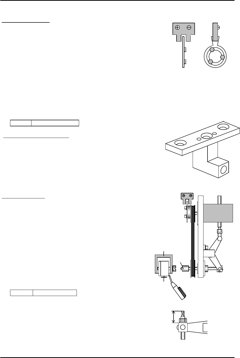
4.11 Station 18 Nozzle Changer Adjustment
NC axis Zero setting
1. Lower the NC servo amp gain to 150 [PN100]
2. Remove the zero setting flag from the drive gear.
3. Remove the timing belt
4. Set the cam to 0 degrees, and complete zero setting.
5. Attach the timing belt so that zero setting completes where
the rotor for the NC clutch faces horizontally. Align the flag
within the center of the sensor
6. Return the NC servo amp gain to 250. [PN100]
<I/O à ETC à Servo brd3 à IN>
SX00E NC AXIS ZERO
Alignment and Belt Tension
1. Align the NC clutch using (Jig no.: 71615WPJ0281) at 200 degrees.
Check the belt tension at the same time.
(Changing the belt tension will shift the alignment.)
(Appropriate value --- 142 +/- 5Hz)
Caution: The alignment jig spans 3 nozzle shafts. Do not
move the jig to the stations where the nozzle shaft moves up and down.
Stroke adjustment
1. After alignment, set a nozzle holder on nozzle shaft, A.
Set the cam angle at station 1 to 200 degrees, and align the
nozzle holder.
2. Move the aligned nozzle holder between station 17 and 18
at 0 degrees. Turn the solenoid valve for the nozzle changer
ON.
3. Turn the index and set the cam angle to 128 degrees.
Adjust the rod so that the nozzle holder clutch pushes
the nozzle changer clutch 0.01 to 0.05mm. (0.03 best)
(The rod length within the cam box must be set to 21mm.)
<I/O à Standard I/O à OUT>
Y02A NOZ SOL ON
4. For the floating angle of the rod-end under the cam box,
fix where it is parallel to the lever and set the rod to 21mm
at the 18
th
station lever.
(LOCTITE, 262) (Torque: 15N.m)
21mm
Figure 24
Figure 25
Figure 27
Nozzle holder
Clutch
NC motor
Figure 26

FK-9F98-05 CP-643E Training Text for Service Engineers
Edition 5.0 Chapter 4. Station Adjustment [12/18]
Fuji Machine Mfg. Co., Ltd. Okazaki
SMT Equipment Quality Assurance Dept.
Technical Support Div. Section No.2
4-
12
NC Data Calibration
1. Set the cam angle to 0 degrees. Turn ON the NC valve.
2. Zero set the NC-axis. Turn OFF the 200V and rotate the index to set the cam angle to 128
degrees.
3. Engage the NC clutch rotor with the nozzle holder clutch.
4. NC data --- Servo counter of the NC-axis where the clutch started engaging and
there is no play in the NC clutch rotate-direction. (It does not matter
whether “plus” or “minus” values are obtained. Take the lowest pulse
count value to get the clutch horizontal.)
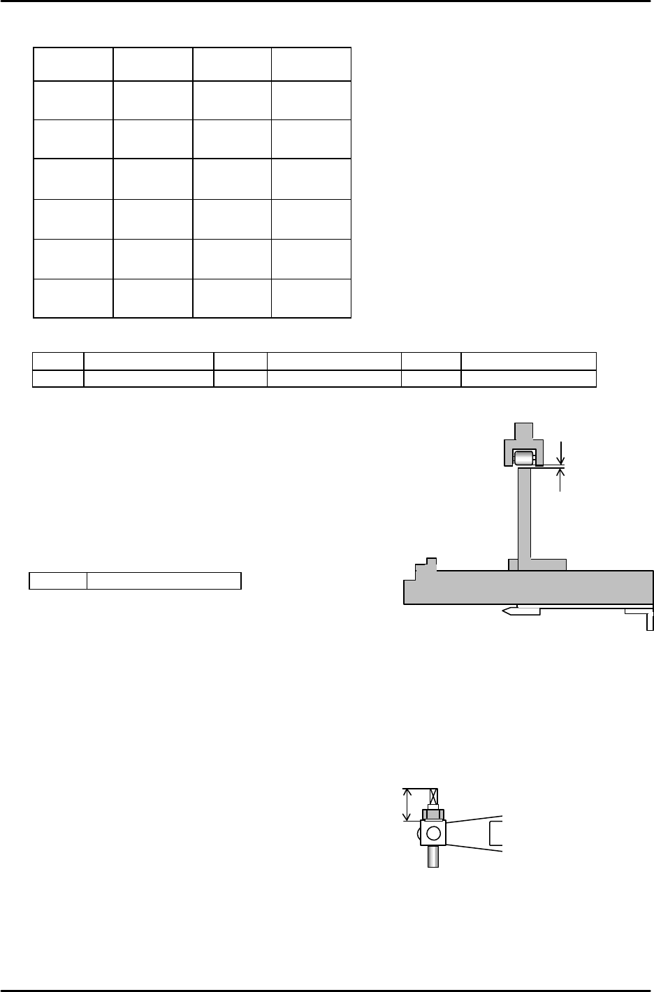
4.12 Stations 17 and 19 Nozzle Type Check Sensor Adjustment
1. Confirm the alignment of each sensor bracket using an alignment jig.
Caution: The alignment jig spans 3 nozzle shafts. Do not move the jig to the stations where the
nozzle shaft moves up and down by nozzle up/down cam.
2. Move the fiber sensor to the end of bracket, and fix it there. (The clearance between the sensor
and dog is about 12mm.)
Setting the amplifier
1. Set a nozzle holder to the nozzle shaft. Set the cam angle to 200 degrees. Align the
nozzle holder at the 11
th
station in the Y direction. Turn OFF the 13 station valve and
remove the spring from the 12
th
station.
2. Select the 6th nozzle, ON, OFF, ON, and move the holder to station 17.
(Cam at 200 degrees.)
3. Set the mode changing switch for the nozzle type check sensor amplifier at station 17 to
“SET”, and press the “TUNING” button. (3 positions)
4. Select the 2nd nozzle, OFF, ON, OFF, and press the “TUNING” button. (3 positions)
5. Set the mode changing switch back to “ RUN”.
6. Digital display after amplifier settings;
( ON, OFF, ON) = (9, 0, 9)
( OFF, ON, OFF) = (0, 9, 0)
7. Adjust the nozzle type check sensor at station 19 in the same manner.
A
1
2
3
4
5
6
Figure 28
FK-9F98-05 CP-643E Training Text for Service Engineers
Edition 5.0 Chapter 4. Station Adjustment [13/18]
Fuji Machine Mfg. Co., Ltd. Okazaki
SMT Equipment Quality Assurance Dept.
Technical Support Div. Section No.2
4-
13
Check if the sensors detect correctly as shown below when other nozzles are selected.
Sensor 1 Sensor 2 Sensor 3
Nozzle
No. 1
9
(ON)
0
(OFF)
9
(OFF)
Nozzle
No. 2
0
(OFF)
9
(ON)
0
(OFF)
Nozzle
No. 3
0
(OFF)
0
(OFF)
9
(ON)
Nozzle
No. 4
9
(ON)
9
(ON)
0
(OFF)
Nozzle
No. 5
0
(OFF)
9
(ON)
9
(ON)
Nozzle
No. 6
9
(ON)
0
(OFF)
9
(ON)
I/O ? Standard I/O ? IN
X04A NOZ CHK ST17 1 X04B NOZ CNK ST17 2 X04C NOZ CHK ST17 3
X04D NOZ CHK ST19 1 X04E NOZ CHK ST19 2 X04F NOZ CHK ST19 3
4.13 Station 1 Tape Feed Adjustment
1. Set the cam angle to 0 degrees, turn the tape feed solenoid valve ON.
2. Move the jig to the parts pick-up position. Adjust the clearance
between the roller and the lever to 0.5mm.
<I/O à Standard I/O à OUT>
Y026 TAPE FD SOL ON
4.14 Waste Tape Cutter Adjustment
1. Confirm that the movable cutter is in contact with the guide roller, and there is no play on both the
right and left sides.
2. Confirm that there is more than 0.2mm clearance between the cutter lever and the guide.
3. Set the rod length within the cam box to 21mm.
4. Set the cam angle to 203 degrees to adjust the cutter stroke. Ensure the position where the
cutter completes engagement. Find the position where the cutter rises 0.5 to 1.0mm from the
engaged position and also where the cutter goes down less than 0.5mm from the bottom of the
cutter plate when the cutter is lowered at 0 degrees.
0.5mm
Jig Z9913AWPJ9310
Figure 29
21mm
Figure 30