CP643E.pdf - 第41页
FK-9F98-05 CP-643E Training Text for Service Engineers Edition 5.0 Chapter 3. X, Y, Z and D-axes Adjustment [ 22 /26] Fuji Machine Mfg. Co., Ltd. Okazaki SMT Equipment Quality Assurance Dept. Technical Support Div. Secti…
FK-9F98-05 CP-643E Training Text for Service Engineers
Edition 5.0 Chapter 3. X, Y, Z and D-axes Adjustment [21/26]
Fuji Machine Mfg. Co., Ltd. Okazaki
SMT Equipment Quality Assurance Dept.
Technical Support Div. Section No.2
3-21
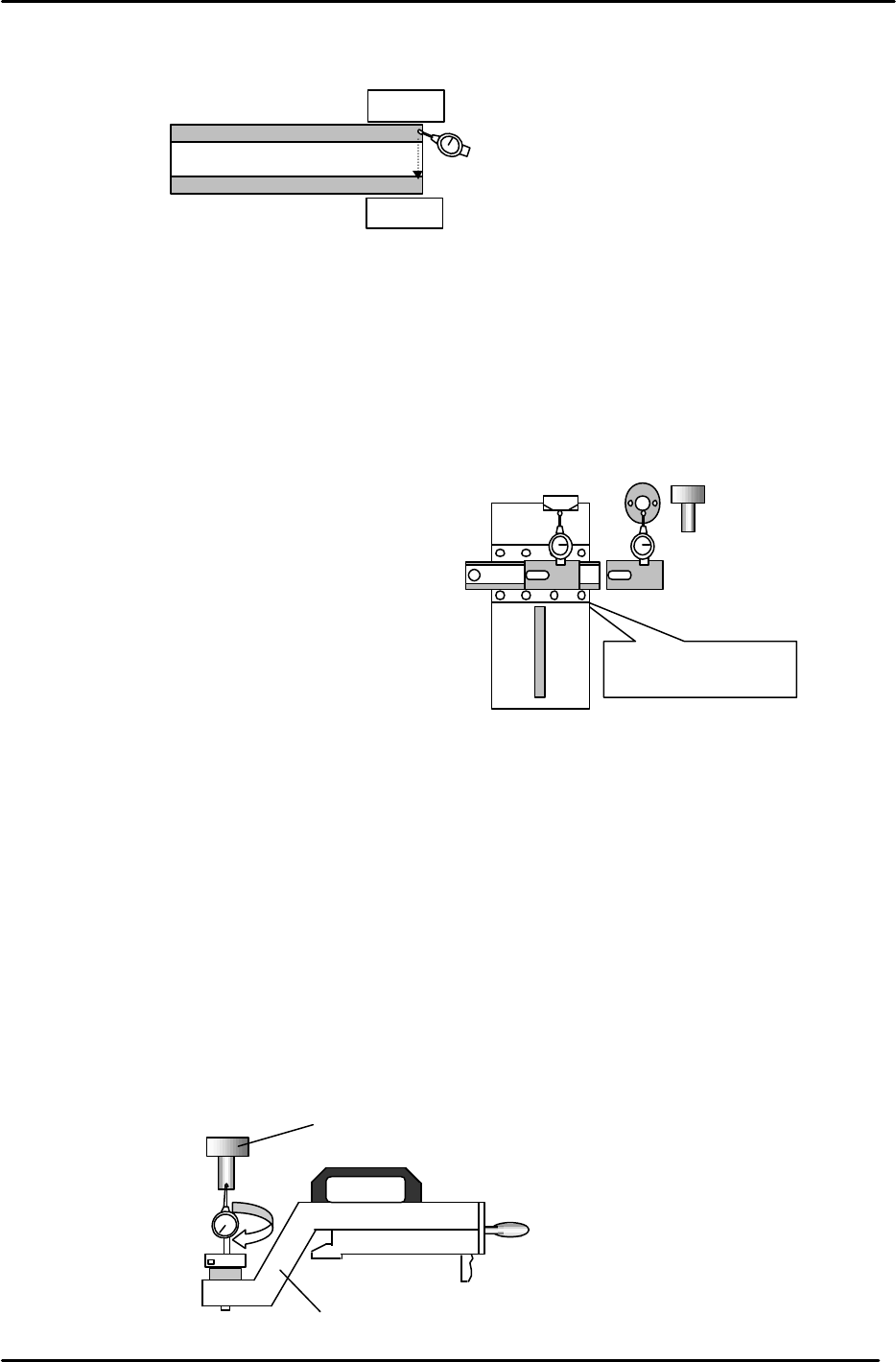
3. Set a dial gauge and block on the machine base and check the flatness from A to B.
(Tolerance: within 0.05mm)
3.17 Cam Box Positioning Check
1. Attach the positioning jig onto the A Shaft and turn the Pick-up valve ON.
2. Position the A shaft at station 1 and set the cam to 200 degrees.
3. Install the cam box alignment jig on the D1 table.
(Tolerance: 0 to + 0.05mm)
4. Check the cam box position at slots 3 & 68 of D1 & D2
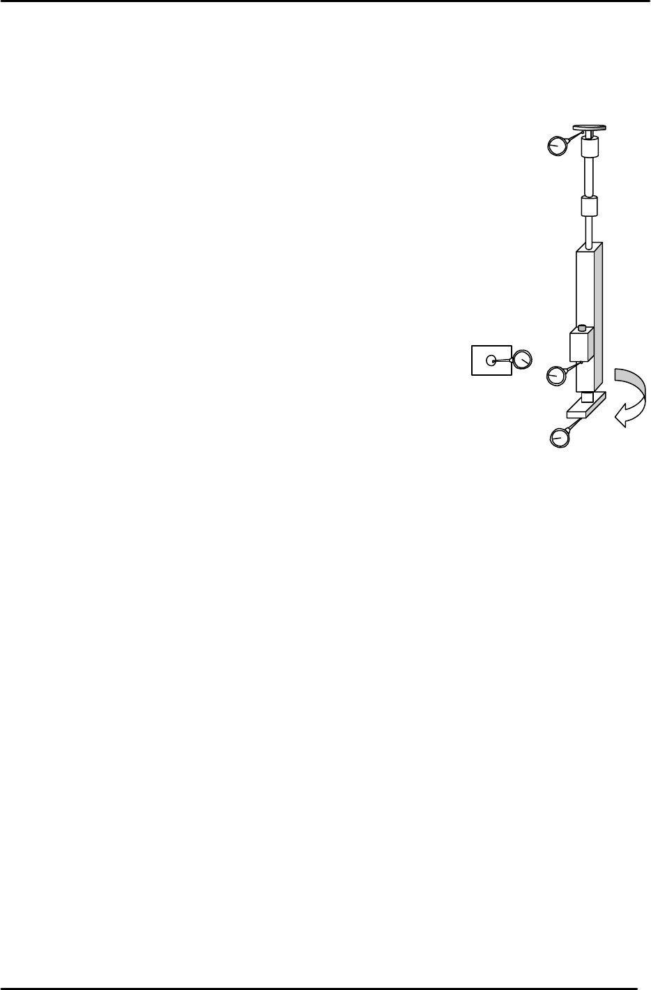
3.18 Pick up Position Calibration
1. Attach the positioning jig onto the A Shaft. (Jig No.:ADCPJ8130)
2. Set the “Pick up Position” jig on the D1/D2 table at slot No.1. (Jig No.:Z9913AWPJ9330)
3. Turn the Pick-up valve ON and set the cam to 170 degrees at Station 1.
4. Balance the dial gauge on both sides of the positioning jig in the X-direction.
When the gauge is balanced on each side, this becomes pick up position D1/D2.
5. When balanced, enter the pulse count into the proper at the host PC.
0
D1 Pallet
A
Dial Gauge Block
Jig No.: Z5313WPJ0070
Figure 34
Do not inch
with
the
jig
attached to the table.
0 to 0.05mm
Cam box alignment
Jig No.: ADCPJ8270
JIG A
(Jig No.: 71615WPJ2070)
Figure 35
Figure 36
“
Pick up
pos
”
jig
(Jig No.: Z9913AWPJ89330)
(Jig No.: 71615WPJ2070)
FK-9F98-05 CP-643E Training Text for Service Engineers
Edition 5.0 Chapter 3. X, Y, Z and D-axes Adjustment [22/26]
Fuji Machine Mfg. Co., Ltd. Okazaki
SMT Equipment Quality Assurance Dept.
Technical Support Div. Section No.2
3-22
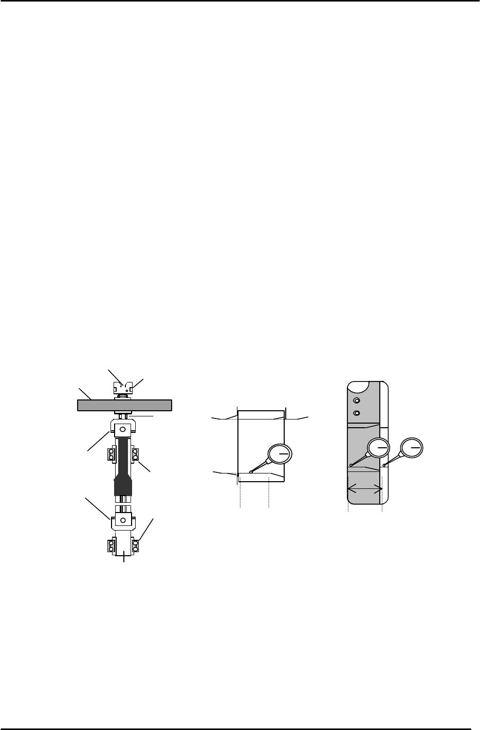
3.19 Shaft Measurement Check
The following procedure explains how to check various items on the nozzle shafts. These
measurements are required when carrying out adjustments in Chapter 5.
1. Set the Cam angle to 0 degrees.
2. Turn the 11
th
station place solenoid ON.
3. Using shaft A as the reference 0, measure the height of the shaft
flange (1) for all the shafts A to T. Measure with the cam at 200
degrees. Push down on the flange slightly with a finger so the
position of the shaft remains consistent.
(Tolerance: < 0.05mm)
Measure both ends of the shaft flange to ensure it is flat; the
difference between the two ends of the flange should be
0.01mm or less.
4. Next, use spool A as the reference and measure the height of
spools A to T. Note that the height of the spool should be
measured when it is at the upper limit (2). Measure at 200
degrees. Push down on the flange slightly with a finger so the
position of the shafts remains consistent.
(Tolerance: < 0.15mm)
5. Next, measure the stroke of the 12
th
station. Measure at 200
degrees. Put the dial gauge in the center of the clutch underside
(3). Find the lowest shaft (the shaft that pushes down the least)
and set the stroke for this shaft within the range of 0.3 to
0.35mm. Note that 0.31mm is the ideal value. Also be aware
that when rotating the shaft the stroke amount will change; set
the stroke where the clutch underside is lowest. When rotating
the shaft, the fluctuation in the stroke amount should be less
than 0.03mm.
6. As mentioned above, the stroke of the lowest shaft should be
within the range of 0.3 to 0.35mm. The stroke of all the other
shafts must be within the range 0.3 to 0.45mm.
7. For the adjustments that follow in Chapter 5, it is necessary to
establish the following three values:
1. Identifying the low shaft. (the clutch which pushes down the least)
2. Identifying the shaft with the average clutch stroke.
3. Identifying the shaft with the low spool valve.
Bottom view of
spool valve.
1
2
3
Figure 37
FK-9F98-05 CP-643E Training Text for Service Engineers
Edition 5.0 Chapter 3. X, Y, Z and D-axes Adjustment [23/26]
Fuji Machine Mfg. Co., Ltd. Okazaki
SMT Equipment Quality Assurance Dept.
Technical Support Div. Section No.2
3-23
3.20 Slider Height Adjustment for ST1, ST11
To set the slider height, it will be necessary to remove a shaft assembly. Choose any shaft other
than the “A” shaft for removal.
1. Move the shaft to be removed near ST11 and set the cam angle to 0 degrees. Place a
8mm spanner at position A and remove the 3mm socket hex bolt from the top of the
clutch. (fig. 38)
2. Remove the four retainers for the linear guide and disconnect the vacuum hose. Remove the
shaft assembly from the index unit.
3. With the Placing and Pick-up valves OFF, move the opening where the shaft was removed to
Station 11 and set the cam at 180 degrees. Check the flatness of the slider surface as
indicated in Fig. 39. (the flatness should be zero) Follow the same procedure for Station 1.
(Pick-up)
4. For stations 1 & 11, turn the cam to zero degrees and turn the placing solenoid ON.
Measure the slider height in relation to the cylindrical cam (with the cam at 10 degrees) as
illustrated in Fig. 40. (10 degrees allows sufficient clearance for the dial gauge)
Adjust the height of the slider for Stations 1 & 11 by adjusting the appropriate rod in the Cam
Box. After adjustment, rotate the cam a few times and return to check the value again. Once
complete, ensure the lock nut is securely tightened on the 1
st
and 11
th
station rods.
Coupling
retainer
A
Helical gear
Clutch
Linear guide rail
3mm socket hex bolt
Figure 38
Tolerance: 0
Figure 39
0
±
0.03mm
(cam at 10 degrees)
Figure 40