CP643E.pdf - 第49页
FK-9F98-05 CP- 643E Training Text for Service Engineers Edition 5.0 Chapter 4. Station Adjustment [ 4 /18] Fuji Machine Mfg. Co., Ltd. Okazaki SMT Equipment Quality Assurance Dept. Technical Support Div. Section No.2 4- …
FK-9F98-05 CP-643E Training Text for Service Engineers
Edition 5.0 Chapter 4. Station Adjustment [3/18]
Fuji Machine Mfg. Co., Ltd. Okazaki
SMT Equipment Quality Assurance Dept.
Technical Support Div. Section No.2
4-
3
4. To check that the clutch and low shaft are properly aligned, measure the difference in stroke when
the shaft is at 0, 90, 180, and 270 degrees. Tolerance is 0.030mm. Adjust bracket (2) if necessary.
5. Once the clutch is aligned within tolerance, proceed to set the 5
th
station stroke.
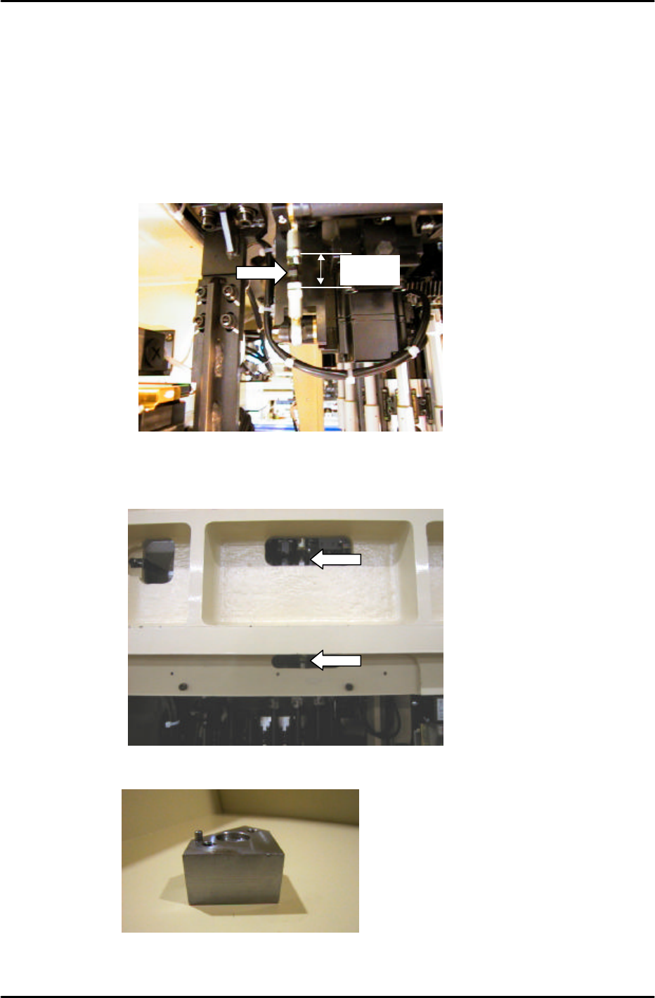
6. Set the length of the stroke-adjusting rod, (located under the cam box at the front of the machine),
to 21mm. (See figure 5 below) When setting the stroke, ensure that the adjustment nut (at the tip
of the arrow), is in the center of the stroke-adjusting rod.
7. With the cam at 200 degrees, set the 5
th
station stroke within a range of 0.30 to 0.35mm, (0.31mm
is the ideal value). Set the stroke by turning the stroke-adjusting rod, (located at the front of the
machine in front of the FQ motor). (See figure 6 below)
8. Once the stroke adjustment is completed, place the 5
th
station origin jig, on shaft A:
Station 5 origin jig Jig No. 71615WPJ0650
Figure 7
Figure 5
21mm
Figure 6
FK-9F98-05 CP-643E Training Text for Service Engineers
Edition 5.0 Chapter 4. Station Adjustment [4/18]
Fuji Machine Mfg. Co., Ltd. Okazaki
SMT Equipment Quality Assurance Dept.
Technical Support Div. Section No.2
4-
4
9. Taking care to ensure that the jig does not interfere with the adjacent shafts, bring shaft A to the
5
th
station at 200 degrees.
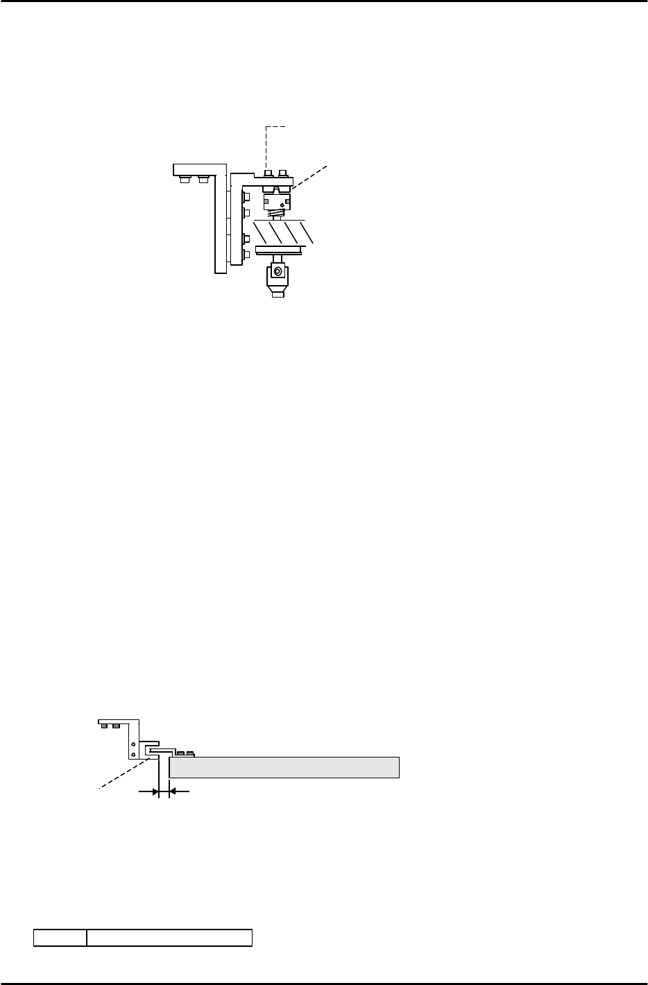
10. Loosen the two 2.5mm cap screws above the fifth station clutch (Fig. 9).
11. Rotate the position of the clutch (1) until the 5
th
station origin jig is parallel to the D axis. Use a
dial gauge on the D axis to measure the surface of the jig. Tolerance is 0.01mm or less.
12. Having locked the two 2.5mm allen cap screws and secured the clutch angle, double check that
the jig is still parallel to the D axis. Do this by rotating the jig back to station 3, then forward to
mesh once again with the 5
th
station at 200 degrees. Take care to ensure that the jig does not
crash into one of the neighboring shafts.
13. Finally, remove the jig before proceeding with the adjustments that follow.
4.4 Head A Check Sensor Adjustment
1. Adjust the position of the sensor bracket so that the head A flag is centered in the sensor at 200
degrees.
2. The target clearance between the sensor and the helical gear is 0.5mm or more.
3. Check sensor reaction in I/O.
<I/O à Standard I/O à IN>
X049 ST 11 HEAD A CHECK
2.5mm
cap screw
1
Figure 8
> 0.5mm
Head A
Sensor
HELICAL GEAR
Figure 9
FK-9F98-05 CP-643E Training Text for Service Engineers
Edition 5.0 Chapter 4. Station Adjustment [5/18]
Fuji Machine Mfg. Co., Ltd. Okazaki
SMT Equipment Quality Assurance Dept.
Technical Support Div. Section No.2
4-
5
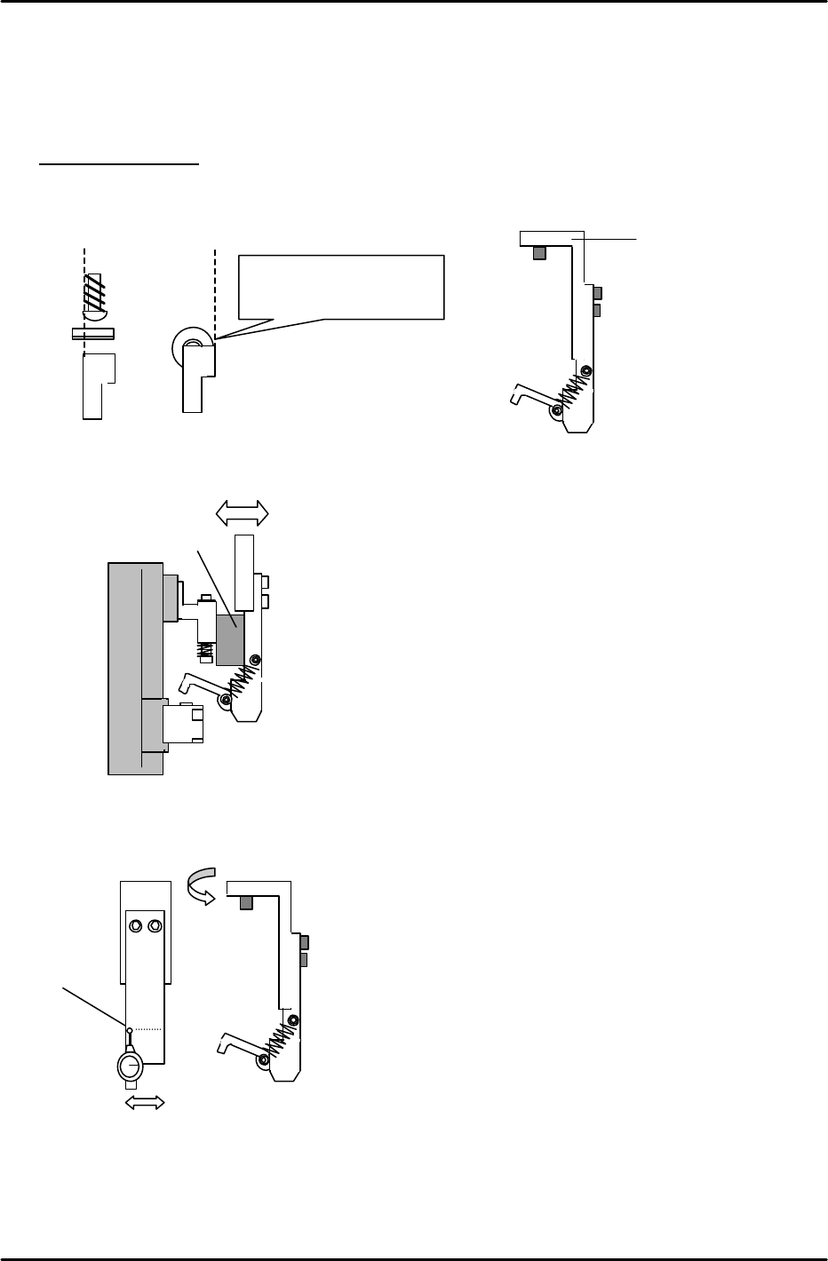
4.5 Mechanical Valve Adjustment at Stations 1 and 11
Raise all spool valves to the upper limit. Calibrate the bottom face using a dial indicator. Identify
the “Low Valve” as the reference. (Previously identified in Chapter 3)
Station 1 Adjustment
1. Install the “L” bracket at station 1. When installing, ensure the lever and right edge of the spool
valve align as indicated. (Cam at 200 degrees)
2. Set the clearence between the sping pin and “L” bracket to 11mm, by moving the “L” bracket in
or out.
3. Align the “L” bracket parallel to the D-axis using a dial gauge as indicated.
4. After completion, re-check steps 1 to 3 to ensure proper alignment.
1
< 0.1mm
Align the right edge of the
spool valve and lever.
“L” Bracket
11mm spacer jig
Figure 10
Figure 11
Figure 12
Figure 13