CP643E.pdf - 第24页
FK-9F98-05 CP-643E Training Text for Service Engineers Edition 5.0 Chapter 3. X, Y, Z and D-axes Adjustment [ 5 /26] Fuji Machine Mfg. Co., Ltd. Okazaki SMT Equipment Quality Assurance Dept. Technical Support Div. Sectio…
FK-9F98-05 CP-643E Training Text for Service Engineers
Edition 5.0 Chapter 3. X, Y, Z and D-axes Adjustment [4/26]
Fuji Machine Mfg. Co., Ltd. Okazaki
SMT Equipment Quality Assurance Dept.
Technical Support Div. Section No.2
3-4
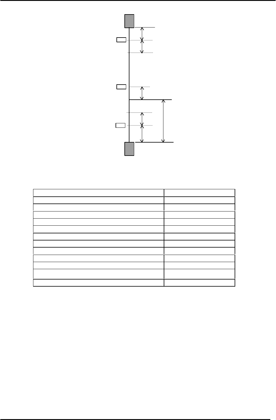
14. The following table lists the Y axis proper and physical data reference values.
Y-axis Servo Count Values
Y-axis Servo Counter Table 0.01mm/Pulse Standard Value
Minus Mechanical Stopper - 500±50
Minus OT Sensor <SX009> - 250±50
Min Limit Pos. Y - 150±50
Zero Set Sensor ON <SX00A> 1000±50
PCB Check Pos. Y (37900)
Loading Pos. YL IN Same value as “YL OUT”
Loading Pos. YL OUT 0±100
Mark Read Pos. Yc (41200)
Placing Pos. Y0 (41400)
Max Limit Pos. Y 41900±200
Plus OT Sensor <SX008> 42000±200
Plus Mechanical Stopper 42100±200
– OT
+ OT
+ Stopper
– Stopper
Zero Set Sensor
Min Limit Position
Max Limit Position
100
0 Position
100
1000
500
250
100
Y axis
Figure 3
FK-9F98-05 CP-643E Training Text for Service Engineers
Edition 5.0 Chapter 3. X, Y, Z and D-axes Adjustment [5/26]
Fuji Machine Mfg. Co., Ltd. Okazaki
SMT Equipment Quality Assurance Dept.
Technical Support Div. Section No.2
3-5
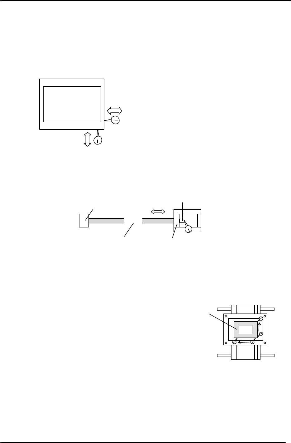
3.4 X and Y Axes Backlash Check
1. Place a (0.002mm) dial gauge against the X-axis of the XY table (Fig.4). Make sure the servo
power is ON, push the XY table left and right by hand to check the amount of backlash.
(Tolerance: 0.010mm.)
2. Check the Y axis in the same manner. Make sure the servo power is ON, push the XY table
backwards and forward to check the amount of backlash. (Tolerance: 0.010mm.)
3. If the amount of backlash is out of tolerance, check the following 2 areas.
a. Ball nut
b. Ball screw bearings
3.5 X/Y Table Squaring Check
Check the squaring of the X/Y table using the jig plate.
(Jig No.: Z9913AWPJ9560)
1. Align the jig in the Y direction to zero using a dial gauge.
2. Indicate the jig face in the X direction to check table squaring.
(Tolerance: 0.015 / 239mm)
XY Table
Backlash check in the X direction
Backlash check in the Y direction
Figure 4
Ball Nut
Bearing
Bearing
Indicate here to check bearings
Coupling box
Figure 5
Squaring Jig
Figure 6
FK-9F98-05 CP-643E Training Text for Service Engineers
Edition 5.0 Chapter 3. X, Y, Z and D-axes Adjustment [6/26]
Fuji Machine Mfg. Co., Ltd. Okazaki
SMT Equipment Quality Assurance Dept.
Technical Support Div. Section No.2
3-6
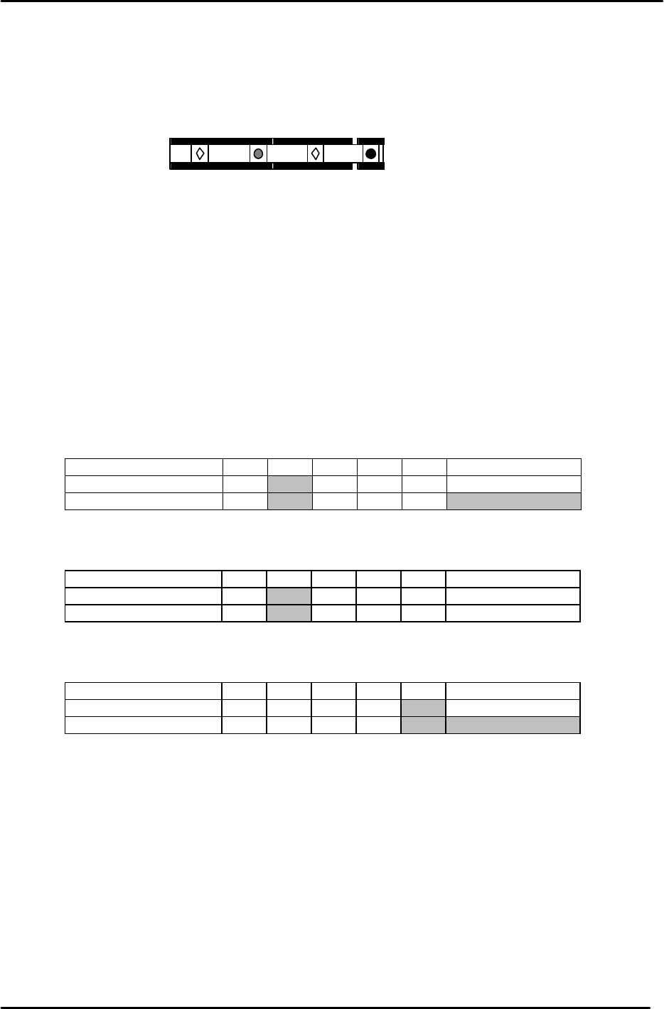
3.6 Reference and Adjustable Pin Alignment Check
Check the alignment and play of the tooling pins as follows.
1. The diagram below shows the tooling pin configuration for the CP-643E.
2. To check the alignment of the four pins, place a dial gauge (0.002mm) against reference pin A
and set it to 0.
3. Inch the X/Y table in the X direction and measure the alignment of the three other pins in
relation to reference pin A .
4. Measure at the points indicated in the tables below:
Measuring Point (mm) Max 370 270 170 70 Reference pin A
Center Position 0
Backlash Value
Measuring Point (mm) Max 370 270 170 70 Reference pin A
Center Position 0
Backlash Value
Measuring Point (mm) Max 370 270 170 70 Reference pin A
Center Position 0
Backlash Value
Secondary Pin A:
Reference Pin B:
Center Position Tolerance: +/- 0.020mm. Backlash Tolerance: 0.040mm.
Secondary Pin B:
Center Position Tolerance: +/- 0.050mm. Backlash Tolerance: 0.040mm.
Center Position Tolerance: +/- 0.050mm. Backlash Tolerance: 0.040mm.
Reference pin A
Reference pin B
Secondary pin A
Secondary pin B
Figure 7