CP643E.pdf - 第16页
FK-9F98-05 CP-643E Training Text for Service Engineers Edition 5.0 Chapter 2. Cam Box Adjustment [ 3 /6] Fuji Machine Mfg. Co., Ltd. Okazaki SMT Equipment Quality Assurance Dept. Technical Support Div. Section No.2 2- 3 …
FK-9F98-05 CP-643E Training Text for Service Engineers
Edition 5.0 Chapter 2. Cam Box Adjustment [2/6]
Fuji Machine Mfg. Co., Ltd. Okazaki
SMT Equipment Quality Assurance Dept.
Technical Support Div. Section No.2
2-2
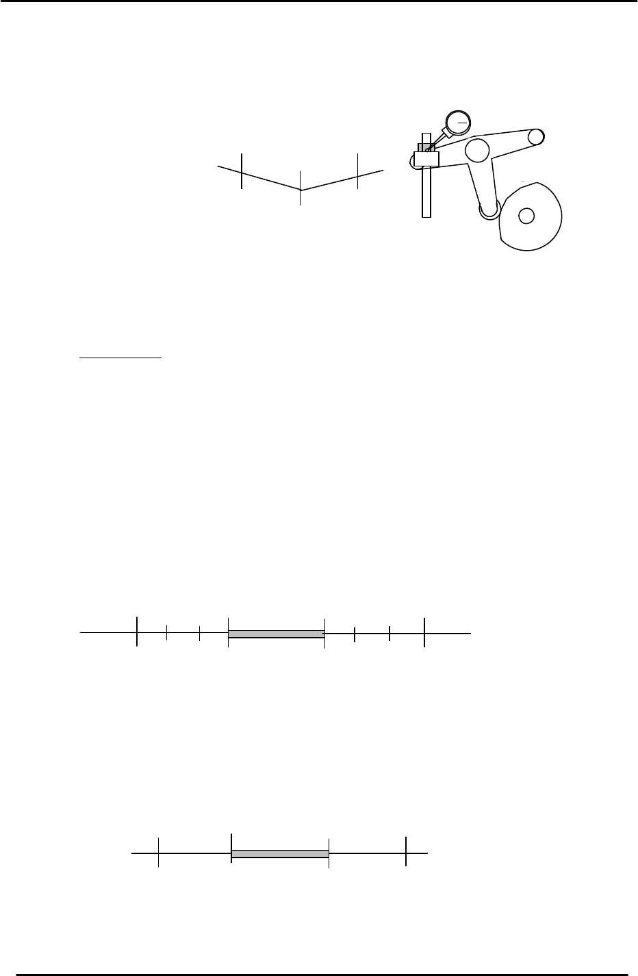
2.4 B-Cam Scale Angle Check (Timing Reference Point)
1. Set a dial indicator on the cam lever of the waste tape cutter (B-axis). Check that the
maximum diameter (low point) of the cam is set to: 203 degrees.
2. When measuring with the dial gauge, find the center point and move the cam lever
0.01mm as indicated above. If the setting is balanced, the readings should be as
indicated. However, if not, move the angle scale so the readings are within range.
IMPORTANT!
The Cam B axis scale is the reference point for all timing within the Cam Box. Be sure
that this adjustment is carried out correctly. Otherwise, the machine timing will be
adversely affected.
2.5 Cam-axis Synchronization (Using B-axis Scale)
1. Set a dial gauge against the nozzle holder. When the nozzle index stops, the cam angle
should be between 130 and 133 degrees. When starting to move, the cam angle should be
between 253 and 256 degrees.
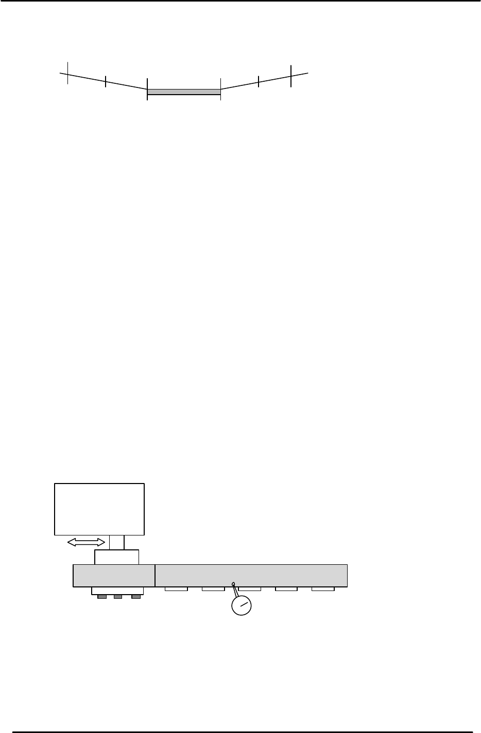
2. Set a dial indicator on the theta index helical gear. When the theta index stops, the cam
angle should be between 74 and 75 degrees. When starting to move, the cam angle should
be between 299 and 300 degrees.
203
199
207
+ 0.01
+ 0.01
Waste Tape Cutter
Figure 2
133
253
(Within 4 degrees on each side)
Starting point
Stopping point
256
130
No movement
range
Figure 3
75
299
300
74
No movement
range
(Within 1 degree on each side)
Stopping point
Starting point
Figure 4
FK-9F98-05 CP-643E Training Text for Service Engineers
Edition 5.0 Chapter 2. Cam Box Adjustment [3/6]
Fuji Machine Mfg. Co., Ltd. Okazaki
SMT Equipment Quality Assurance Dept.
Technical Support Div. Section No.2
2-3
3. Set a dial indicator on the FRQ cam lever (Station 12). Make sure that when the cam lever is at
the low point, the cam axis is between 107 and 267 degrees.
4. After checking the above, ensure the A-axis scale matches the B-axis reference scale.
Notes:
1. In all cases above, the maximum difference between the stopping and starting points
should be within +/- 1 degrees.
Example: If the nozzle index stops at 122 degrees it should begin moving at 254 +/-
1degree.
2. The exact timing of movement varies a little from machine to machine. (but still within
tolerance). The main point is to ensure that the stopping and stating points are
balanced.
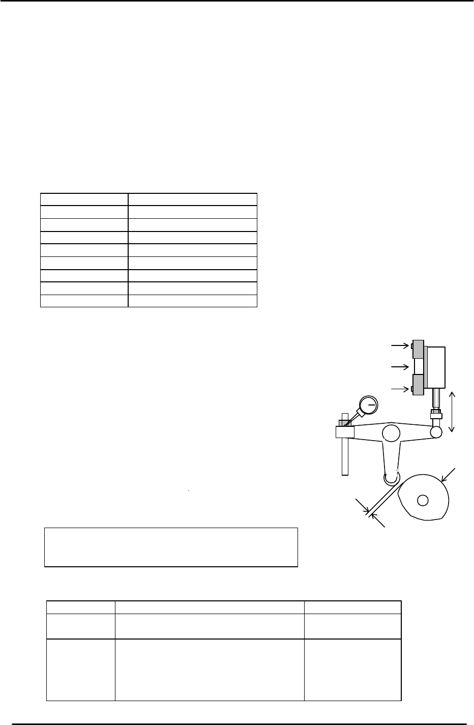
2.6 Helical Gear Backlash Check
1. Check the backlash of the large helical gear using a dial indicator with shafts A, F, K, and P at
station 11. (180 degrees)
2. The backlash between the two helical gears should be within 0.030 to 0.080mm.
3. The backlash may be adjusted by moving the theta index unit to the right or left.
107
267
269
105
No movement
range
(Within 2 degrees on each side)
Stopping point
Starting point
Figure 5
Theta Index Unit
Figure 6
FK-9F98-05 CP-643E Training Text for Service Engineers
Edition 5.0 Chapter 2. Cam Box Adjustment [4/6]
Fuji Machine Mfg. Co., Ltd. Okazaki
SMT Equipment Quality Assurance Dept.
Technical Support Div. Section No.2
2-4
2.7 3st PQ and 13st PRQ Cylinder Rod Adjustment
1. Release the air and make sure that the cam follower is in contact with both sides of the barrel
cam when the angle is at 257 degrees. If not, adjust the stroke of the cylinder rod end.
2. Set the air regulator in the cam box to 0.4MPa. Tighten the lock nut and mark with a white
marker.
3. Check each cylinder sensor. The sensor must turn ON when the cam angle is between 210 to
212 degrees. (Ensure that the cam follower moves to the right when both PQ and PRQ rotate
90 degrees, and moves to the left when rotated 270 degrees.)
<I/O à Standard à (IN or OUT)>
OUT - Y024 PQ ROT, 90 DEG
OUT - Y025 PQ ROT, 270 DEG
IN - X045 PQ ROT, 90 DEG
IN - X044 PQ ROT, 270 DEG
OUT - Y02E PRQ ROT, 90 DEG
OUT - Y02F PRQ ROT, 270 DEG
IN - X051 PRQ ROT, 90 DEG
IN - X050 PRQ ROT, 270 DEG
2.8 Cam Lever Stopper Adjustment
1. Adjust the Cam lever stopper at stations 1, 3, 10, 11, 13
and 18.
2. Turn each station’s solenoid valve ON at zero degrees.
(The cam will be in contact with the cam roller when the
solenoid valve is ON, and apart when the valve is OFF.)
3. Set a dial gauge on the cam lever to measure the
clearance at each valve location.
4. When the solenoid valve is OFF, adjust the air cylinder
stroke so that the dial indicator reads within the ranges
shown below.
<I/O à Standard I/O à OUT>
Station I/O port Appropriate Value
1 ST
11 ST
OUT - Y020 PICKUP SOL ON
OUT - Y028 PLACE SOL ON
0.05 to 0.07mm
3 ST
10 ST
13 ST
18 ST
1ST feeding
OUT - Y022 PQ ROT SOL ON
OUT - Y030 FQ SOL ON
OUT - Y02C PRQ ROT SOL ON
OUT - Y02A NOZ SOL ON
OUT - Y026 TAPE FEED SOL ON
0.10 to 0.15mm
The solenoid valve must be OFF
,
except when
making adjustments. [Top= ON] [Bottom = Off]
ON
OFF
Solenoid Valve
Clearance
CAM
Figure 7