CP643E.pdf - 第22页
FK-9F98-05 CP-643E Training Text for Service Engineers Edition 5.0 Chapter 3. X, Y, Z and D-axes Adjustment [ 3 /26] Fuji Machine Mfg. Co., Ltd. Okazaki SMT Equipment Quality Assurance Dept. Technical Support Div. Sectio…
FK-9F98-05 CP-643E Training Text for Service Engineers
Edition 5.0 Chapter 3. X, Y, Z and D-axes Adjustment [2/26]
Fuji Machine Mfg. Co., Ltd. Okazaki
SMT Equipment Quality Assurance Dept.
Technical Support Div. Section No.2
3-2
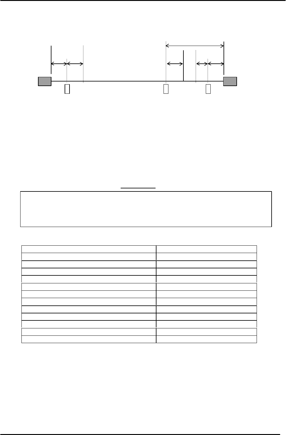
13. Move the X-axis back 100 pulses from where the + OT sensor turns ON and set the proper
value. (Set the Min Limit Position at the host PC)
14. The following table lists the X axis proper and physical data reference values.
IMPORTANT
Be aware that the (+) and (-) signs appear opposite between mechanical check mode and
normal operation for the X-axis counter.
This table represents the pulse count values using normal operation mode.
X-axis Servo Count Values
X-axis Servo Counter Chart 0.01mm/Pulse Standard Value
Plus Mechanical Stopper
300±50 (500 +/- 50, 1 stopper)
Minus OT Sensor <SX004> 250±50
Max Limit Pos. X 150±50
Zero Set Sensor <SX006> – 1000±50
PCB Check Pos. X (– 29200)
Loading Pos. XL IN (– 57960)
Loading Pos. XL OUT (– 6010)
Mark Read Pos. Xc (– 45060)
Placing Pos. X0 (– 57900)
Min Limit Pos. X – 58650±200
Plus OT Sensor ON <SX005> – 58750±200
Minus Mechanical Stopper
– 59000±200
– OT
+ OT
+ Stopper
– Stopper
Zero Set Sensor
Min Limit Position
Max Limit Position
X- axis
100
0 Position
100
1000
1300
50
250
Figure 1
FK-9F98-05 CP-643E Training Text for Service Engineers
Edition 5.0 Chapter 3. X, Y, Z and D-axes Adjustment [3/26]
Fuji Machine Mfg. Co., Ltd. Okazaki
SMT Equipment Quality Assurance Dept.
Technical Support Div. Section No.2
3-3
3.3 Y-axis Zero setting (0.01mm/pulse)
1. Ensure that the Y-axis motor is NOT inclined or tilted.
2. Make sure that the zero setting and OT sensors are not blocked by the flags.
3. Carry out Y-axis zero setting by mechanical check mode. ( Y-axis motor rotates)
4. In Mecha-check mode, complete zero setting by blocking the zero set sensor with a scale.
5. Set the servo counter value to 22000 pulses.
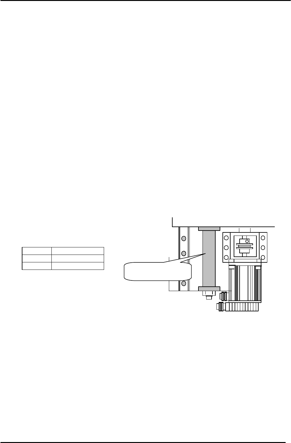
6. Place the coupling tightening jig (211mm) between the Y-axis mechanical stopper and Y-axis
base. Tighten the coupling bolt to a torque value of 7Nm.
7. Press the emergency stop button and bring the Y-axis to the minus mechanical stopper. Record
the servo counter value. (To bring the value close to – 500 pulses, offset the 22000 pulses in
step 5.)
8. Set the servo counter to plus 1000 pulses. Adjust the flag to turn the zero set sensor ON at this
position. Record the servo counter value.
9. Adjust the flag to turn the minus over travel sensor ON when bringing the flag 250 pulses back
from the minus mechanical stopper. Record the servo counter value.
10. Record the servo counter value when the table is in contact with the plus mechanical stopper.
Adjust the sensor position to turn the plus over travel sensor ON when bringing the flag 100
pulses back. Record the servo counter value.
11. Confirm sensor reaction by I/O.
<I/O à ETC à Servo 2 à IN>
SX008 Y AXIS +OT
SX009 Y AXIS – OT
SX00A Y AXIS ZERO
12. Set the software travel limits as follows:
Move the Y-axis back 100 pulses from where the + OT sensor turns ON and set the proper
value. (Set the Max Limit Position at the host PC)
13. Move the Y-axis forward 100 pulses from where the – OT sensor turns ON and set the proper
value. (Set the Min Limit Position at the host PC)
211mm Spacer jig
Figure 2
Jig No.:WPJ4081
FK-9F98-05 CP-643E Training Text for Service Engineers
Edition 5.0 Chapter 3. X, Y, Z and D-axes Adjustment [4/26]
Fuji Machine Mfg. Co., Ltd. Okazaki
SMT Equipment Quality Assurance Dept.
Technical Support Div. Section No.2
3-4
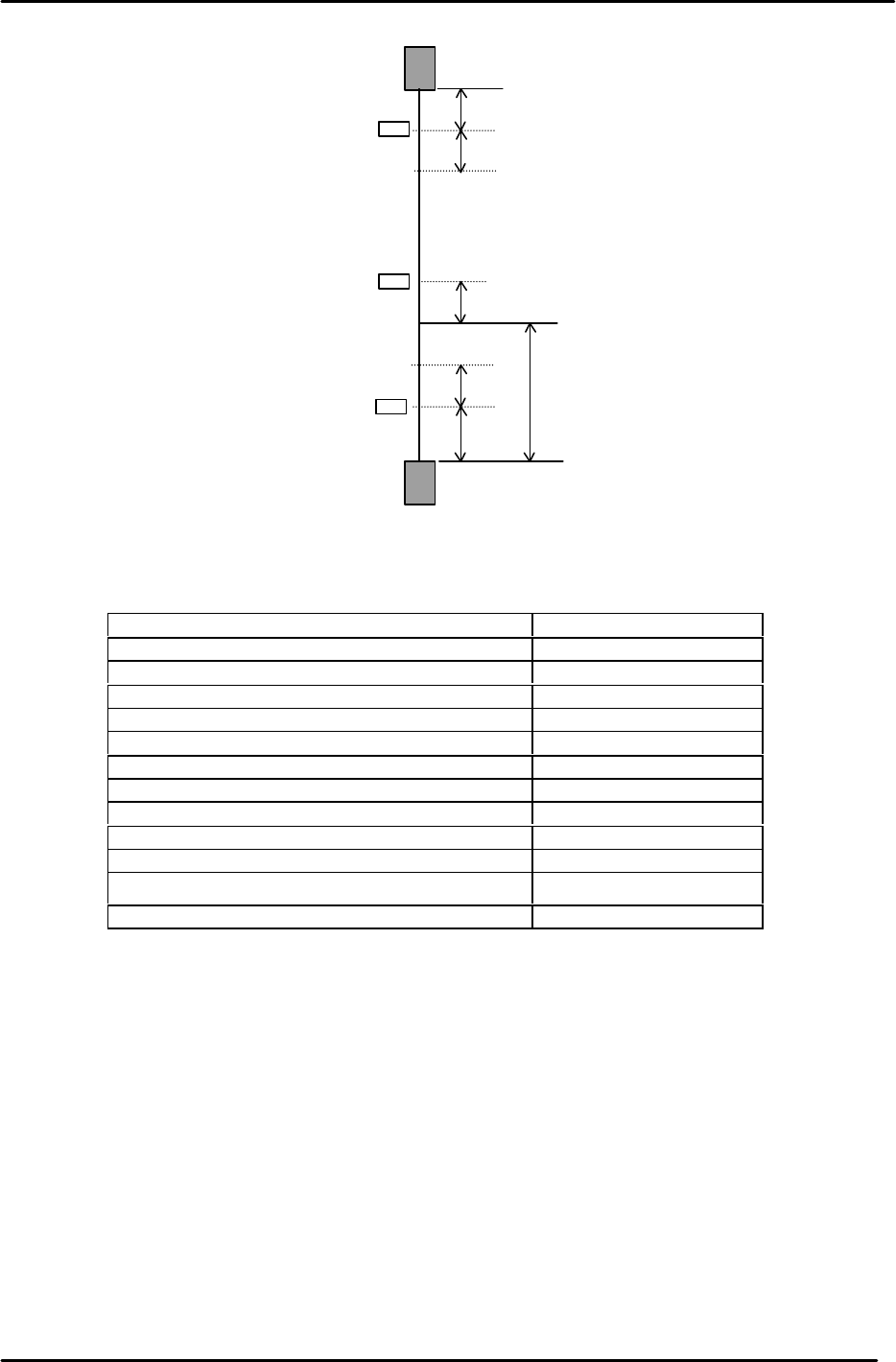
14. The following table lists the Y axis proper and physical data reference values.
Y-axis Servo Count Values
Y-axis Servo Counter Table 0.01mm/Pulse Standard Value
Minus Mechanical Stopper - 500±50
Minus OT Sensor <SX009> - 250±50
Min Limit Pos. Y - 150±50
Zero Set Sensor ON <SX00A> 1000±50
PCB Check Pos. Y (37900)
Loading Pos. YL IN Same value as “YL OUT”
Loading Pos. YL OUT 0±100
Mark Read Pos. Yc (41200)
Placing Pos. Y0 (41400)
Max Limit Pos. Y 41900±200
Plus OT Sensor <SX008> 42000±200
Plus Mechanical Stopper 42100±200
– OT
+ OT
+ Stopper
– Stopper
Zero Set Sensor
Min Limit Position
Max Limit Position
100
0 Position
100
1000
500
250
100
Y axis
Figure 3