CP643E.pdf - 第114页
FK-9F98- 05 CP- 643E Training Text for Service Engineers Edition 5.0 Chapter 7. Camera Adjustment [ 9 / 10] Fuji Machine Mfg. Co., Ltd. Okazaki SMT Equipment Quality Assurance Dept. Technical Support Div. Section No.2 7-…

FK-9F98-05 CP-643E Training Text for Service Engineers
Edition 5.0 Chapter 7. Camera Adjustment [8/10]
Fuji Machine Mfg. Co., Ltd. Okazaki
SMT Equipment Quality Assurance Dept.
Technical Support Div. Section No.2
7-8
7.6 Gain Adjustment
1. Insert a clean 0.7mm nozzle in holder A, nozzle 1. Ensure that the reflective seal is properly flattened
down.
2. Inch the nozzle to station 6 at 200 degrees.
3. Press SET à MANUAL à VISION à TRACE à ID code to turn on “RESULT, No.0”.
4. Adjust the gain volume to set both narrow and wide cameras to between 0.65 and 0.7mm, 650 and
700. (Target value = 675.) This value can be seen on the monitor while running the center test.
5. When the 0603 camera has been installed;
The measurement value should be 0.37mm to 0.4mm [Display : 370 to 400 (Target value = 385)]
IMPORTANT:
The resolution values will change if the camera gain is changed. So it is necessary to check the
camera resolution again if the gain has been changed. If the resolution is out of tolerance, adjust the
camera positioning again.
FK-9F98-05 CP-643E Training Text for Service Engineers
Edition 5.0 Chapter 7. Camera Adjustment [9/10]
Fuji Machine Mfg. Co., Ltd. Okazaki
SMT Equipment Quality Assurance Dept.
Technical Support Div. Section No.2
7-9
7.7 Mark Camera Adjustments
7.7.1 Focus Adjustment
Note that before adjusting the mark camera the X0Y0 and the Z0 adjustments must already be
completed, and the proper data input into the machine.
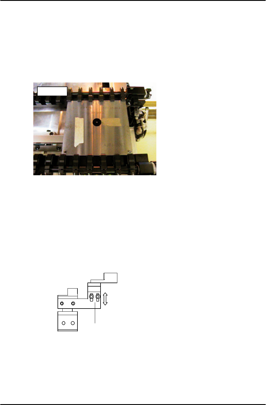
1. Clamp the fiducial jig plate in the main conveyor clamper. Make sure that the two tooling pins fit
smoothly into the two holes in the jig plate. (figure 16)
2. Move the fiducial jig plate under the mark camera by inching. Set the height of the main table to Z0
as follows:
[SET] → [PROPER] → [CAMERA] → [XC/YC] → [Z0] → START
NOTE: Z0 must be calibrated before carrying out this adjustment. When focusing the mark camera,
make sure the table is set at Z0.
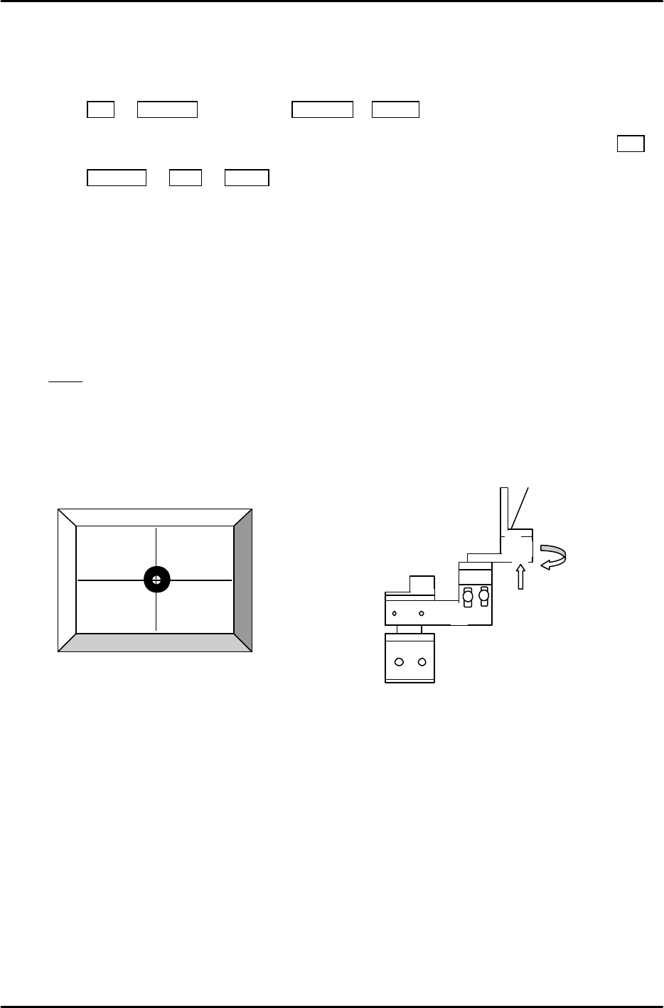
3. Loosen the two height positioning bolts and adjust the focus by raising or lowering the height of the
camera. (see figure 17)
4. The focus is set when the black circle and silver dot in the center of the mark camera jig are in
clear, sharp focus.
AJPJ0062
Figure 16
2 height
adjustment
bolts.
Figure 17
FK-9F98-05 CP-643E Training Text for Service Engineers
Edition 5.0 Chapter 7. Camera Adjustment [10/10]
Fuji Machine Mfg. Co., Ltd. Okazaki
SMT Equipment Quality Assurance Dept.
Technical Support Div. Section No.2
7-10
7.7.2 Mark Camera Resolution, Skew, and XC YC Calibration
1. Set the table height to Z0. Clamp the XcYc jig using pins at Z0.
2. Press SET à PROPER à ID code à CAMERA à XC/YC.
3. Jog to align the mark on the XcYc jig with the crosshairs on the monitor (fig.18) then press SET.
4. Press RETURN à Mark à START. The resolution and delta will be measured for the mark
camera.
5. Rotate the camera bracket (fig.19) in order to set Delta Q to 0. Then repeat from step 2 again.
(Tolerance ----- less than ±0.05 deg.
Mark camera resolution ----- 18.2 to 19.3 um/pixel
Mark Read Pos Xc should be in the following range:
Mark Read Pos Xc – 45100 to – 45300 (L à R flow) , – 400 to – 600 (RàL flow)
Note! If the PCB was reverse flow, R? L, (reference pin position = left), add 10000 pulses to XC.
6. If outside the prescribed range, loosen the focus adjustment bolts and adjust the height of the
camera. Re-measure the resolution and repeat until the values fall within range.
2 adjustment
bolts here.
Figure 19
Figure 18