CP643E.pdf - 第50页
FK-9F98-05 CP- 643E Training Text for Service Engineers Edition 5.0 Chapter 4. Station Adjustment [ 5 /18] Fuji Machine Mfg. Co., Ltd. Okazaki SMT Equipment Quality Assurance Dept. Technical Support Div. Section No.2 4- …
FK-9F98-05 CP-643E Training Text for Service Engineers
Edition 5.0 Chapter 4. Station Adjustment [4/18]
Fuji Machine Mfg. Co., Ltd. Okazaki
SMT Equipment Quality Assurance Dept.
Technical Support Div. Section No.2
4-
4
9. Taking care to ensure that the jig does not interfere with the adjacent shafts, bring shaft A to the
5
th
station at 200 degrees.
10. Loosen the two 2.5mm cap screws above the fifth station clutch (Fig. 9).
11. Rotate the position of the clutch (1) until the 5
th
station origin jig is parallel to the D axis. Use a
dial gauge on the D axis to measure the surface of the jig. Tolerance is 0.01mm or less.
12. Having locked the two 2.5mm allen cap screws and secured the clutch angle, double check that
the jig is still parallel to the D axis. Do this by rotating the jig back to station 3, then forward to
mesh once again with the 5
th
station at 200 degrees. Take care to ensure that the jig does not
crash into one of the neighboring shafts.
13. Finally, remove the jig before proceeding with the adjustments that follow.
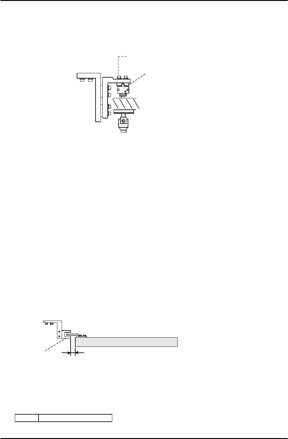
4.4 Head A Check Sensor Adjustment
1. Adjust the position of the sensor bracket so that the head A flag is centered in the sensor at 200
degrees.
2. The target clearance between the sensor and the helical gear is 0.5mm or more.
3. Check sensor reaction in I/O.
<I/O à Standard I/O à IN>
X049 ST 11 HEAD A CHECK
2.5mm
cap screw
1
Figure 8
> 0.5mm
Head A
Sensor
HELICAL GEAR
Figure 9
FK-9F98-05 CP-643E Training Text for Service Engineers
Edition 5.0 Chapter 4. Station Adjustment [5/18]
Fuji Machine Mfg. Co., Ltd. Okazaki
SMT Equipment Quality Assurance Dept.
Technical Support Div. Section No.2
4-
5
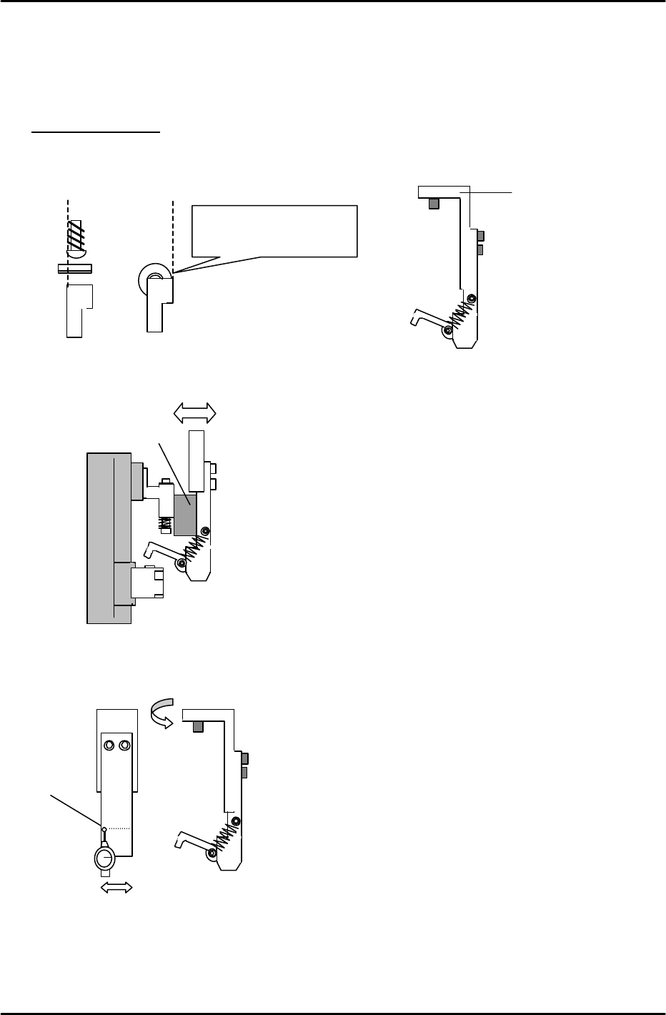
4.5 Mechanical Valve Adjustment at Stations 1 and 11
Raise all spool valves to the upper limit. Calibrate the bottom face using a dial indicator. Identify
the “Low Valve” as the reference. (Previously identified in Chapter 3)
Station 1 Adjustment
1. Install the “L” bracket at station 1. When installing, ensure the lever and right edge of the spool
valve align as indicated. (Cam at 200 degrees)
2. Set the clearence between the sping pin and “L” bracket to 11mm, by moving the “L” bracket in
or out.
3. Align the “L” bracket parallel to the D-axis using a dial gauge as indicated.
4. After completion, re-check steps 1 to 3 to ensure proper alignment.
1
< 0.1mm
Align the right edge of the
spool valve and lever.
“L” Bracket
11mm spacer jig
Figure 10
Figure 11
Figure 12
Figure 13
FK-9F98-05 CP-643E Training Text for Service Engineers
Edition 5.0 Chapter 4. Station Adjustment [6/18]
Fuji Machine Mfg. Co., Ltd. Okazaki
SMT Equipment Quality Assurance Dept.
Technical Support Div. Section No.2
4-
6
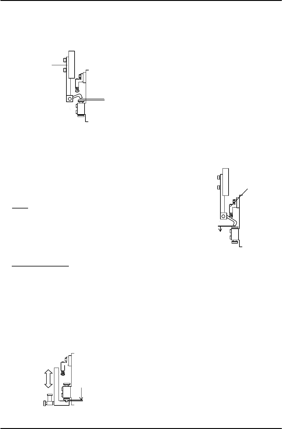
5. Move the “Low Valve” shaft to station 1. Turn OFF the Pick-up Valve. Set the cam angle to
175 degrees. Adjust the clearance between the pushed up spool and lever to 0.7mm by
moving part [A ] vertically.
6. Set the cam angle back to 0 degrees, and turn ON the Pick-up Valve. (Y020)
7. Set the cam angle to 175 degrees. Adjust part, [B] vertically to
set the clearance between the mechanical valve and the lever
at 0 to 0.1mm. (0.07mm best condition) Adjust all other shafts in
the same manner.
NOTE
* Confirm that the spool does not interfere with the lever.
* Do not push the mechanical valve too much.
* Adjust only after completing the pickup height adjustment.
Station 11 Adjustment
1. Move the “Low Valve” shaft to station 11. Set the cam at 0 degrees. Turn ON the Placing
valve. (Y028)
2. Set the cam at 200 degrees and set the clearance between the low valve and bracket at
0.05 to 0.1mm. Align the hole in the lever assembly with the mechanical valve.
3. Confirm that the clearance between the lever and valve is NOT 0 on all shafts
4. Open the speed controller 4.5 revolutions away from the fully closed position.
Place Valve ON
0.05 to 0.1mm
Pick
-
up
Valve
OFF
0.7mm
[A]
Figure 14
Figure 16
Pick-up Valve ON
0 to 0.1mm
Figure 15
[B]