CP643E.pdf - 第44页
FK-9F98-05 CP-643E Training Text for Service Engineers Edition 5.0 Chapter 3. X, Y, Z and D-axes Adjustment [ 25 /26] Fuji Machine Mfg. Co., Ltd. Okazaki SMT Equipment Quality Assurance Dept. Technical Support Div. Secti…
FK-9F98-05 CP-643E Training Text for Service Engineers
Edition 5.0 Chapter 3. X, Y, Z and D-axes Adjustment [24/26]
Fuji Machine Mfg. Co., Ltd. Okazaki
SMT Equipment Quality Assurance Dept.
Technical Support Div. Section No.2
3-24
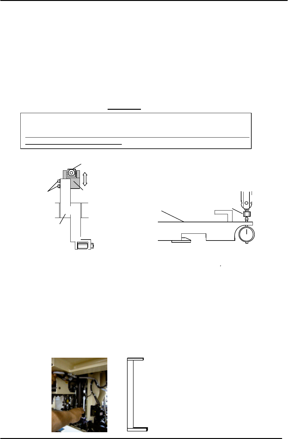
3.21 Station 1 Pickup Height Adjustment
1. Set the cam angle to 0 degrees and turn the 1st station pickup valve ON. (Y020)
2. Install a nozzle jig in nozzle holder, No.1. (fig.42) Set the cam to 175 degrees.
3. Loosen the cam lever stroke adjustment bolts and move the fulcrum (fig. 41) so the dial
gauge reads zero. (Zero indicates that the pickup height is 0.650mm.) The tolerance for
all shafts must be 0.65 +/- 0.05. (check all shafts)
4. After adjustment, go back and check that the slider height is within tolerance.
(0 +/-0.03mm)
Important
Whenever the pickup height is adjusted, the slider height must be checked again.
Adjust both the pickup height and slider height until they are both within tolerance.
Exercise extreme care when setting the pick-up height. Mis-adjustment can lead to
component cracking during pick-up.
3.22 Reattaching the Shaft Assembly
When the slider height adjustment has been completed, reattach the shaft in the reverse order as
it was removed.
1. Tighten the retainer installation bolts using a torque wrench as follows.
(Torque the top 3mm bolts to 2 N.m, Torque the bottom 4mm bolts to 4N.m)
2. Using the bar jig, re-install the shaft assembly and align the holder and clutch so the alignment jig
inserts smoothly between the holder and the clutch. (there should be NO resistance) It is
important for all shafts and clutches to be aligned properly in order to avoid problems later on.
Nozzle No. 1
Nozzle jig
Jig Z9064ALPJ5540
Master gauge
Cam lever
Stroke adjusting bolt
Rod
Fulcrum
Figure 41
Figure 42
19
TH
station alignment Jig No. WPJ0102
Figure 43
FK-9F98-05 CP-643E Training Text for Service Engineers
Edition 5.0 Chapter 3. X, Y, Z and D-axes Adjustment [25/26]
Fuji Machine Mfg. Co., Ltd. Okazaki
SMT Equipment Quality Assurance Dept.
Technical Support Div. Section No.2
3-25
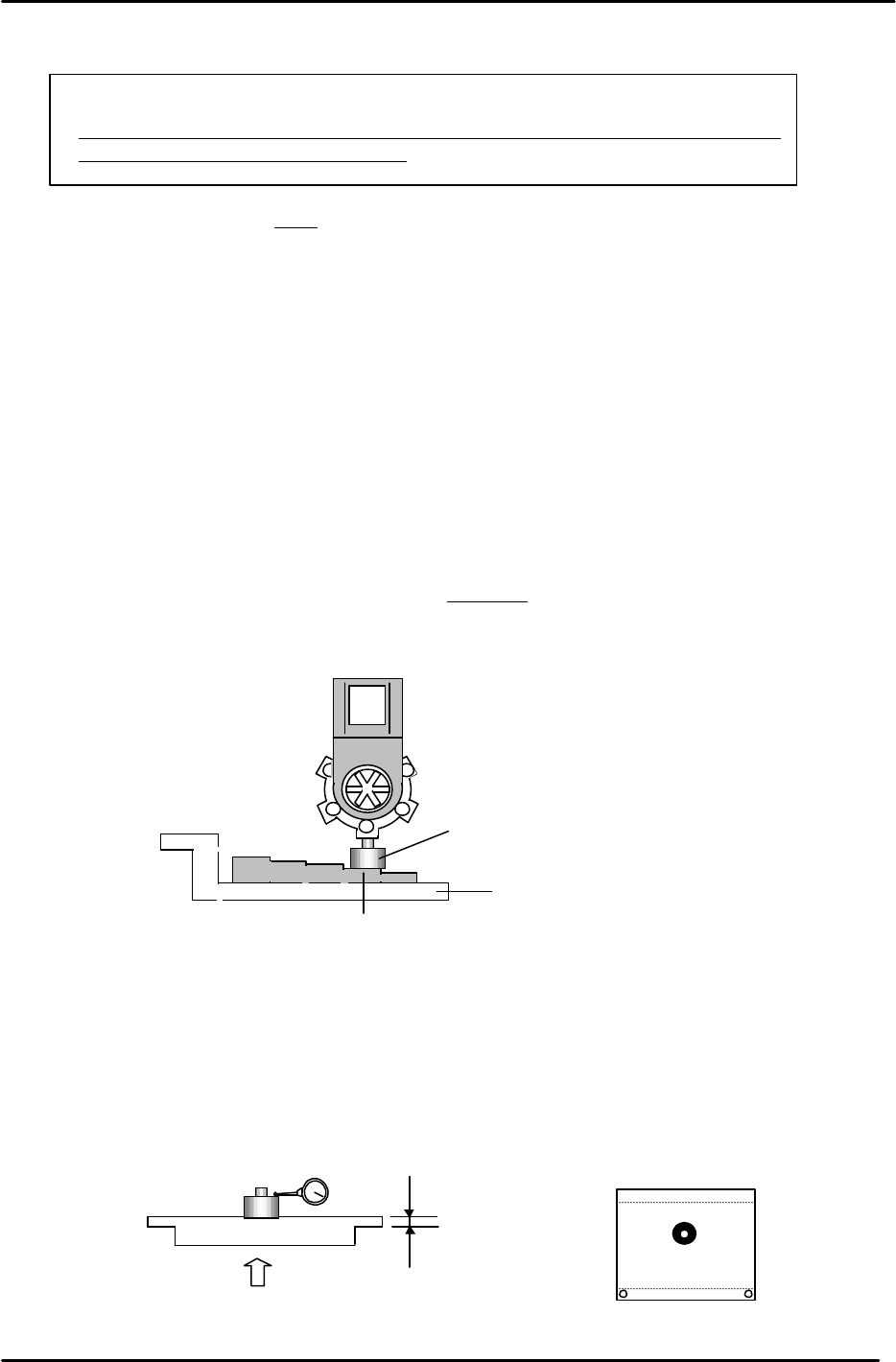
3.23 Placing Height Z0 Calibration
IMPORTANT!!!!
Exercise extreme care when setting the Z-origin height. Mis-adjustment can lead to
component cracking during placement.
NOTE: Calibrate only after the ST11 slider height and main conveyor clamper claws have been
adjusted.
1. Turn the 11
st
solenoid valve ON at 0 degrees.
Y028 PLACE SOL ENGAGED
2. After the Z- Axis adjustment is completed, clamp the jig plate in the middle of the table, and install
the nozzle jig in the A holder.
3. Manually move the jig under the ST11, placing point.
4. Set the cam angle at 200 degrees to lower the nozzle jig. Manually raise the Z-axis so that the
nozzle jig is in contact with a feeler gauge jig (- 0.3mm). The Z-axis servo counter at this time is Z0.
Target: (5500 +/-300 pulses)
5. Calibrate “Z0” on the reference side, adjustable side and center of the jig plate. The deviation
between each measuring point should be within 50 pulses of each other.
6. Enter the average value (of the three measurement points) in the proper at the host PC.
7. Alternatively, clamp the XC/YC calibration plate in the center of the table. Raise the Z-axis until the
dial gauge deflects 0.03mm. The proper value will be the servo pulse count with the gauge
deflected 0.3, plus 1050 (thickness of the jig plate). This procedure works well resulting in basically
the same value as obtained using the procedure in steps 1 to 6.
A
- 0.3mm
Nozzle Jig No.:71615WPJ0082
Jig No.: Z9913AWPJ9460
Figure 44
2.1mm
2.1/ 0.002 = 1050
0.3mm
Jig No.: AJPJ0062
Figure 45
FK-9F98-05 CP-643E Training Text for Service Engineers
Edition 5.0 Chapter 3. X, Y, Z and D-axes Adjustment [26/26]
Fuji Machine Mfg. Co., Ltd. Okazaki
SMT Equipment Quality Assurance Dept.
Technical Support Div. Section No.2
3-26
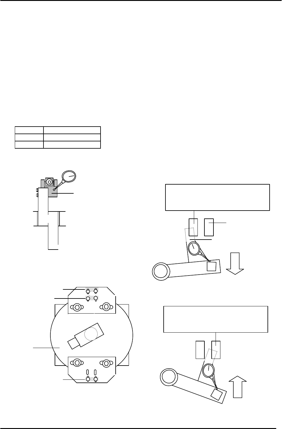
3.24 Upward and Downward End Sensor Adjustment (Stations 1 & 11)
1. Set the cam angle to 0 degrees. Turn the Pick-up (Y020) and Placing valves ON. (Y028)
2. Set a dial indicator at the tip of the cam lever (fig. 46) Turn the cam until the dial gauge deflects 0.30
to 0.40. Adjust the sensor bracket so the sensor turns OFF between 0.30 to 0.40. (fig. 48)
3. Set the cam angle to 200 degrees to adjust the downward end sensor. The downward end sensor is
ON when the lever ascends 0.30 to 0.40mm. Adjust the sensor bracket to turn OFF this sensor.
(fig.49)
4. Adjust the upward end sensor for the 1st in the same manner. (It is not possible to adjust if the flag
is installed at an angle.
5. Confirm sensor reaction in I/O.
<I/O à Standard I/O à IN>
X03F ST11 DN POS
X06A ST1 UP POS
X06B ST11 UP POS
Note: for further details on this adjustment, refer to the CP-6 Series Reference Manual.
Place the dial gauge here
Figure 46
Down end sensor
Up end sensor
Station 11
Station 1
Nozzle index unit
Up end sensor
Figure 47
The down end sensor should turn
OFF when the lever lifts 0.3 to
0.4mm from 200 degrees.
Figure 49
Sensor flag
Down end sensor
The up end sensor should turn
OFF when the lever lowers 0.3 to
0.4mm from 0 degrees.
Figure 48