CP643E.pdf - 第33页
FK-9F98-05 CP-643E Training Text for Service Engineers Edition 5.0 Chapter 3. X, Y, Z and D-axes Adjustment [ 14 /26] Fuji Machine Mfg. Co., Ltd. Okazaki SMT Equipment Quality Assurance Dept. Technical Support Div. Secti…
FK-9F98-05 CP-643E Training Text for Service Engineers
Edition 5.0 Chapter 3. X, Y, Z and D-axes Adjustment [13/26]
Fuji Machine Mfg. Co., Ltd. Okazaki
SMT Equipment Quality Assurance Dept.
Technical Support Div. Section No.2
3-13
12. Lift the Z-axis to the + mechanical stopper and ensure the pulse count is within the following
range.
(CP-643E) 23650±250
13. Check the sensor reaction in I/O.
<I/O à ETC à Servo 1 à IN>
SX00C Z AXIS + OT
SX00D Z AXIS – OT
SX00E Z AXIS ZERO
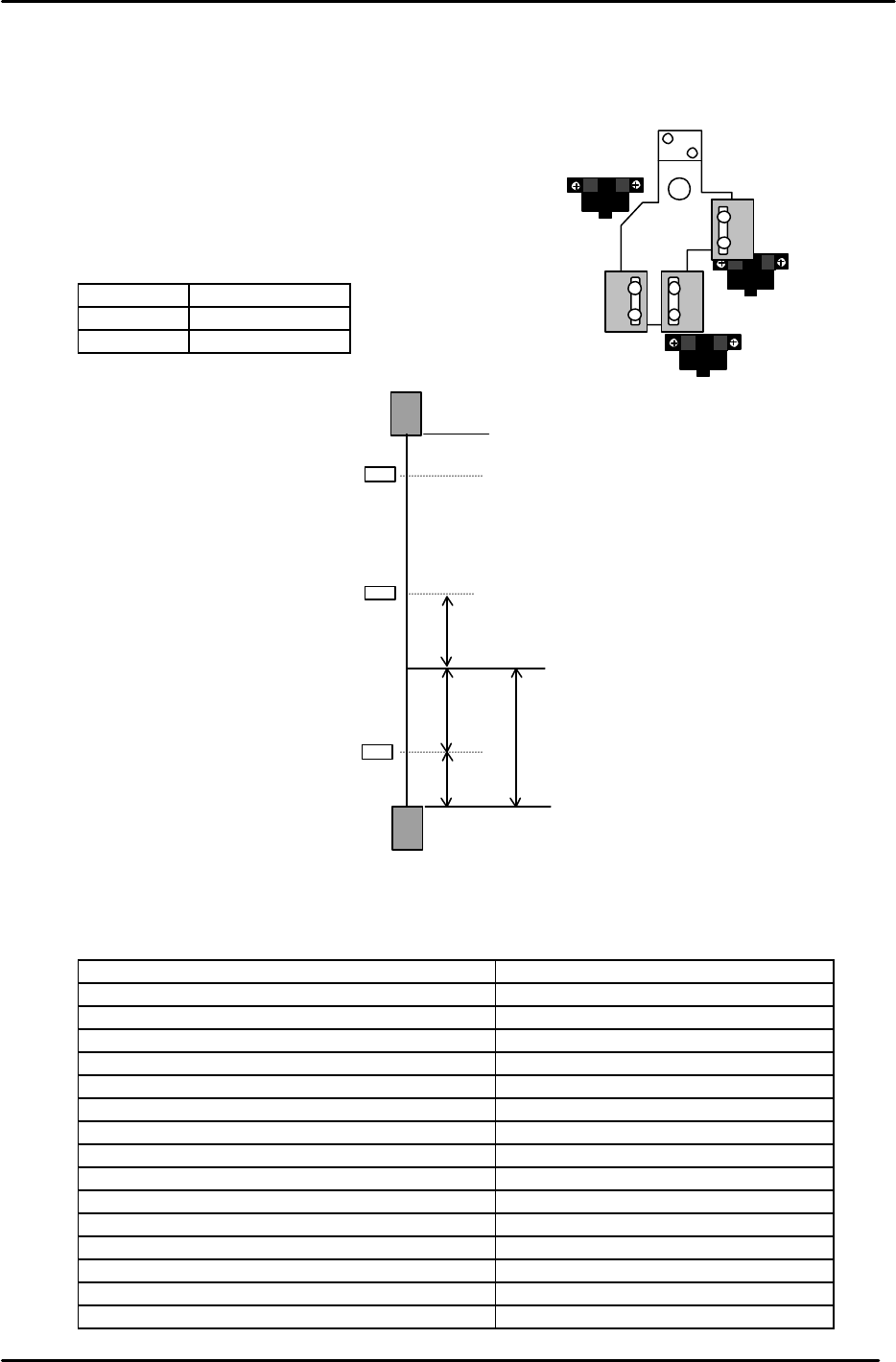
14. The following table lists the Z axis proper and physical data reference values.
Z-axis Servo Count Values
Z-axis Servo counter table 0.002mm/Pulse Standard Value (Reference value)
Plus Mechanical Stopper 23650±250
Max Limit Pos. Z Same as plus OT sensor value
Plus OT Sensor <SX00C> {ZL (Upper) +500}+/-50
Loading Pos. ZL IN 22400 to 22900
Loading Pos. ZL OUT 22400 to 22900
Middle Loading Pos. ML ZL (Lower) – 10500
Upward End Sensor 1 ON ML –125±50
Upward End Sensor 2 ON Z0 + 2300±50
Downward End Sensor OFF Z0 + 400±50
Middle OT Sensor ON Z0 + 150±50
Z0 5500±300
Zero Set Sensor ON <SX00E> 1000±50
Minus OT Sensor ON <SX00D> – 500±50
Min Limit Pos. Z Same as minus OT sensor value
Minus Mechanical Stopper – 1000±50
Zero set sensor
+OT sensor
- OT sensor
Figure 19
– OT
+ OT
+ Stopper
– Stopper
Zero Set Sensor
(Min Limit Position)
(Max Limit Position)
500
0 Position
1000
1000
500
Z axis
Figure 19
{ZL (Upper)
+
500 pulses} +/- 50 pulses
Note: ZL upper is calculated in chapter 5.
Set the maximum limit after determining
the ZL upper position.
FK-9F98-05 CP-643E Training Text for Service Engineers
Edition 5.0 Chapter 3. X, Y, Z and D-axes Adjustment [14/26]
Fuji Machine Mfg. Co., Ltd. Okazaki
SMT Equipment Quality Assurance Dept.
Technical Support Div. Section No.2
3-14
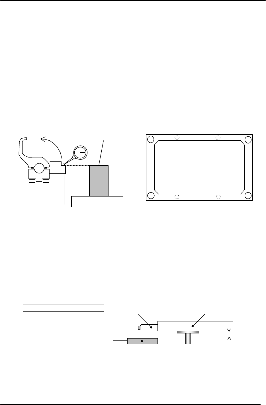
3.10 Back-up Plate Height and Flatness Adjustment
1. After zero-setting the Z-axis, raise the table to 5000 pulses. Place the height
adjustment jig on the backup plate.
2. Adjust the 4 bolts so the top surface of the jig and clamper base are equal.
3. Note: When changing the Z-axis position, the spring force to the plate changes
and the jig’s height will slightly differ. Please pay attention when adjusting.
(Adjust it within range so that the Z-axis and backup plate are synchronized.)
4. Flatness tolerance ----- less than 0.1mm
(There are 4 adjustment bolts. It is better to set one height as reference and measure with a
dial gauge.)
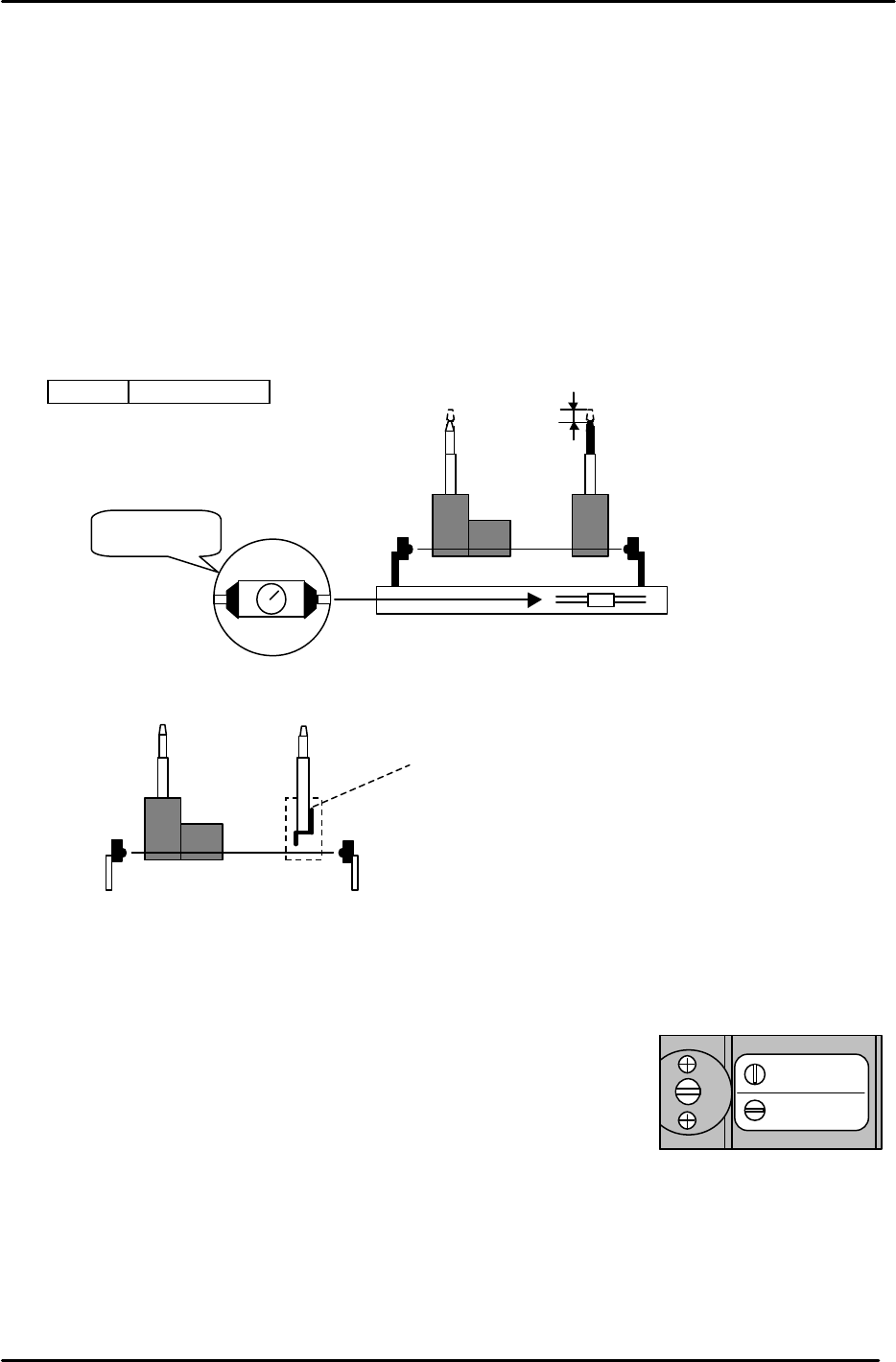
3.11 Back-up Pin Interference Prevention Sensor Adjustment
1. Adjust the 4 flags so the sensors will turn ON, when the clearance between the Y-table and the
backup plate is 2mm. (Set the flags so the 4 sensors activate within 50 pulses of each other.)
2. Check the sensor reaction in I/O.
<I/O ? Standard I/O? IN>
X031 Back up Pin Check
Back up plate
Jig
Z5313WPJ0130
Figure 20
Figure 21
Adjustment bolts
Adjustment bolts
Backup Plate
Flag
Proximity SW
2mm
Figure 22
FK-9F98-05 CP-643E Training Text for Service Engineers
Edition 5.0 Chapter 3. X, Y, Z and D-axes Adjustment [15/26]
Fuji Machine Mfg. Co., Ltd. Okazaki
SMT Equipment Quality Assurance Dept.
Technical Support Div. Section No.2
3-15
3.12 PCB Set Check Sensor Adjustment
1. Adjust the sensor BKT so that the light axis comes to the center of the reference pin
and secondary pin block hole.
2. Set the sensor so it turns OFF when both the reference and adjustable pins move down
1.0 to 1.5mm.
3. As for the adjustable pin, the sensor should react at maximum, mid and minimum
pitches. Make sure that the green LED is always on.
4. Check the sensor reaction in I/O
< I/O à Standard I/O à IN>
X033 PCB SET OK
3.13 Main Conveyor PCB Clamping Claw Check and Adjustment
3.13.1 (Part 1) Claw Positioning Adjustment
1. Check that the reference pin switch valve is set to “Mark Ref”.
2. Lock the rail-clamping claw at the closed position by solenoid valve.
3. Check that all the individual claws are loose.
4. There is some play in the position of the rail-clamping claw center bracket, so check that this is set
at the center of the play.
5. The next step is to lock all the individual claws. When these are locked, the clearance between the
tip of the claw and the guide rail should be in the range of 0.03 – 0.10 mm. (A) Each claw should be
locked using a 4Nm torque wrench. However, before proceeding to lock each claw, there are some
other considerations to bear in mind. Refer to figure 25.
Mark Ref.
Pin Ref.
Figure 24
1.0 to 1.5mm
M
AX
MIN
Set to MAX.
Figure 23
When the pin is pressed
down this flag cuts the
sensor beam. When
replacing the pin ensure that
the flag is long-side up.