CP643E.pdf - 第13页
FK-9F98-05 CP- 643E Training Text for Service Engineers Edition 5.0 Chapter 1. Initial Set-up [ 2 / 2 ] Fuji Machine Mfg. Co., Ltd. Okazaki SMT Equipment Quality Assurance Dept. Technical Support Div. Section No.2 1- 2 N…
FK-9F98-05 CP-643E Training Text for Service Engineers
Edition 5.0 Chapter 1. Initial Set-up [1/2]
Fuji Machine Mfg. Co., Ltd. Okazaki
SMT Equipment Quality Assurance Dept.
Technical Support Div. Section No.2
1-1
Chapter 1 Initial Set-up
1.1 Machine Leveling
Equipment: 0.02mm/1m track level
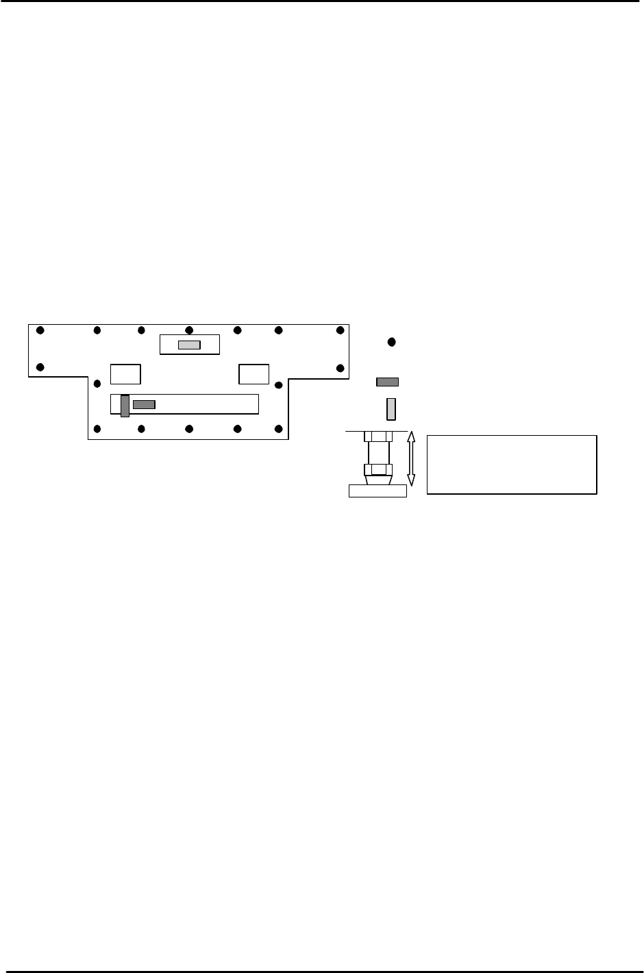
1. Level the machine by placing leveling blocks at the positions illustrated below.
2. Use bolts A, B, E, and F, for initial leveling.
3. Confirm leveling in the X and Y directions once all the bolts have been securely
tightened.
4. Once the initial leveling is completed, lock the remaining bolts shown in the
diagram below.
1.2 Machine Utilities
Refer to the CP-6 series Mechanical Reference Manual for information regarding the utility
connections needed for this machine.
• Power
• Air
For stability reasons, it is
better to keep the leveling
bolts as short as possible.
Leveling positions.
= Spirit Level (tolerance 0.04/1000mm)
= Spirit Level (tolerance 0.08/1000mm)
A B
I
H
G
C
D
E
CP-643E
J
K
L M
N
P
O
F
Figure 1

FK-9F98-05 CP-643E Training Text for Service Engineers
Edition 5.0 Chapter 1. Initial Set-up [2/2]
Fuji Machine Mfg. Co., Ltd. Okazaki
SMT Equipment Quality Assurance Dept.
Technical Support Div. Section No.2
1-2
Notes:

FK-9F98-05 CP-643E Training Text for Service Engineers
Edition 5.0 Chapter 2. Cam Box Adjustment [1/6]
Fuji Machine Mfg. Co., Ltd. Okazaki
SMT Equipment Quality Assurance Dept.
Technical Support Div. Section No.2
2-1
Chapter 2 Cam Box Checks and Adjustments
2.1 Interference Check
1. With the cam angle at 0 degrees, check all stations for interference before turning the cam.
2. As a precaution, it is best not to connect the air supply before adjustment of step 2.8 as some
stations may interfere if the air cylinder is not adjusted correctly.
3. Lower the vacuum switching brackets at stations 11 and 16 to ensure sufficient clearance when
the cam is rotated.
4. Check for interference between the various sensors and their flags before rotating the cam. Pay
special attention to station 1 and station 11 nozzle up & down detection sensor and flag located in
the cam box. Also, check the station 1 waste tape cutter upper and lower limit detection sensors
located (near the dump parts box) at station 16.
5. Secure the Station 1 vacuum switching lever so that it does not interfere with the top surface of
the mechanical valve.
2.2 Cam Box Check
1. Check for any dust, tools, or other foreign matter within the Cam box.
2. Perform an initial check of all bolts and connectors to ensure they are tight.
2.3 Securing the Motor Coupling and Mechanical Locks
1. Use a torque wrench to tighten the motor coupling and mechanical locks.
A: Motor coupling 33N.m
B: Mechanical Lock (M4) 17N.m
B
B
B
B
B
A
Figure 1
M/C Front
CAM A
CAM B