CP643E.pdf - 第14页
FK-9F98-05 CP-643E Training Text for Service Engineers Edition 5.0 Chapter 2. Cam Box Adjustment [ 1 /6] Fuji Machine Mfg. Co., Ltd. Okazaki SMT Equipment Quality Assurance Dept. Technical Support Div. Section No.2 2- 1 …

FK-9F98-05 CP-643E Training Text for Service Engineers
Edition 5.0 Chapter 1. Initial Set-up [2/2]
Fuji Machine Mfg. Co., Ltd. Okazaki
SMT Equipment Quality Assurance Dept.
Technical Support Div. Section No.2
1-2
Notes:
FK-9F98-05 CP-643E Training Text for Service Engineers
Edition 5.0 Chapter 2. Cam Box Adjustment [1/6]
Fuji Machine Mfg. Co., Ltd. Okazaki
SMT Equipment Quality Assurance Dept.
Technical Support Div. Section No.2
2-1
Chapter 2 Cam Box Checks and Adjustments
2.1 Interference Check
1. With the cam angle at 0 degrees, check all stations for interference before turning the cam.
2. As a precaution, it is best not to connect the air supply before adjustment of step 2.8 as some
stations may interfere if the air cylinder is not adjusted correctly.
3. Lower the vacuum switching brackets at stations 11 and 16 to ensure sufficient clearance when
the cam is rotated.
4. Check for interference between the various sensors and their flags before rotating the cam. Pay
special attention to station 1 and station 11 nozzle up & down detection sensor and flag located in
the cam box. Also, check the station 1 waste tape cutter upper and lower limit detection sensors
located (near the dump parts box) at station 16.
5. Secure the Station 1 vacuum switching lever so that it does not interfere with the top surface of
the mechanical valve.
2.2 Cam Box Check
1. Check for any dust, tools, or other foreign matter within the Cam box.
2. Perform an initial check of all bolts and connectors to ensure they are tight.
2.3 Securing the Motor Coupling and Mechanical Locks
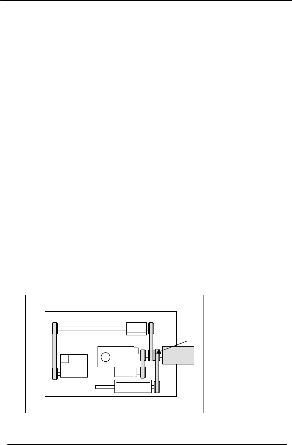
1. Use a torque wrench to tighten the motor coupling and mechanical locks.
A: Motor coupling 33N.m
B: Mechanical Lock (M4) 17N.m
B
B
B
B
B
A
Figure 1
M/C Front
CAM A
CAM B
FK-9F98-05 CP-643E Training Text for Service Engineers
Edition 5.0 Chapter 2. Cam Box Adjustment [2/6]
Fuji Machine Mfg. Co., Ltd. Okazaki
SMT Equipment Quality Assurance Dept.
Technical Support Div. Section No.2
2-2
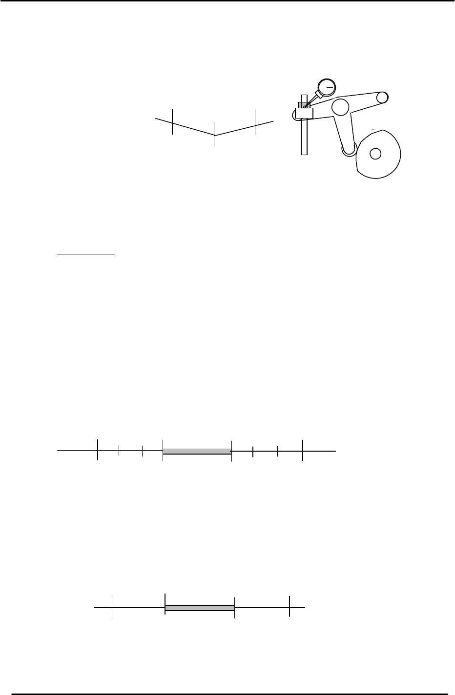
2.4 B-Cam Scale Angle Check (Timing Reference Point)
1. Set a dial indicator on the cam lever of the waste tape cutter (B-axis). Check that the
maximum diameter (low point) of the cam is set to: 203 degrees.
2. When measuring with the dial gauge, find the center point and move the cam lever
0.01mm as indicated above. If the setting is balanced, the readings should be as
indicated. However, if not, move the angle scale so the readings are within range.
IMPORTANT!
The Cam B axis scale is the reference point for all timing within the Cam Box. Be sure
that this adjustment is carried out correctly. Otherwise, the machine timing will be
adversely affected.
2.5 Cam-axis Synchronization (Using B-axis Scale)
1. Set a dial gauge against the nozzle holder. When the nozzle index stops, the cam angle
should be between 130 and 133 degrees. When starting to move, the cam angle should be
between 253 and 256 degrees.
2. Set a dial indicator on the theta index helical gear. When the theta index stops, the cam
angle should be between 74 and 75 degrees. When starting to move, the cam angle should
be between 299 and 300 degrees.
203
199
207
+ 0.01
+ 0.01
Waste Tape Cutter
Figure 2
133
253
(Within 4 degrees on each side)
Starting point
Stopping point
256
130
No movement
range
Figure 3
75
299
300
74
No movement
range
(Within 1 degree on each side)
Stopping point
Starting point
Figure 4