CP643E.pdf - 第75页
FK-9F98-05 CP- 643E Training Text for Service Engineers Edition 5.0 Chapter 5. Loader and Conveyor Adjustment [ 12 / 28 ] Fuji Machine Mfg. Co., Ltd. Okazaki SMT Equipment Quality Assurance Dept. Technical Support Div. S…
FK-9F98-05 CP-643E Training Text for Service Engineers
Edition 5.0 Chapter 5. Loader and Conveyor Adjustment [11/28]
Fuji Machine Mfg. Co., Ltd. Okazaki
SMT Equipment Quality Assurance Dept.
Technical Support Div. Section No.2
5-
11
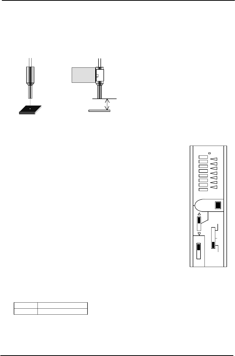
5.14 Loading Position Check Sensor
1. For both the IN and OUT loading positions, adjust the bracket so that the light beam from the
sensor is centered on the silver area of the dog when the XY-table is at each loading position.
2. Set the clearance between the sensor and the dog to 11.5mm. The sensor shall be ON only at the
silver area. If not, adjust the amplifier sensitivity or sensor positioning.
<<Instructions for adjusting the Loading Position Check Sensor>>
“OMRON E3X-NH11”
1. Set to “L_ON”.
2. Set to “ADJ”. Adjust ? , ? or “SET” button so that the red lamp
comes to the center position.
3. Set to “TEACH”. Position the sensor beam over the silver area
on the sticker. Press “SET” once.
4. Position the sensor beam over the black area on the sticker. Press
“SET” once.
5. Set to “RUN”.
<<CHECK>>
1. The red lamps change in volume between ON and OFF conditions.
2. All green lamps will light when the sensor beam light is
positioned over the silver area.
3. One green lamp will light when the sensor beam light is
positioned over the black area.
4. Confirm sensor reaction by I/O.
<I/O à Standard I/O à IN>
X068 XY IN L POS
X069 XY OUT L POS
11.5mm
CE
ADJ
OUT
SET
TEAC
H
RUN
D.
ON
L
ON
E3X- NH11
Figure 19
FK-9F98-05 CP-643E Training Text for Service Engineers
Edition 5.0 Chapter 5. Loader and Conveyor Adjustment [12/28]
Fuji Machine Mfg. Co., Ltd. Okazaki
SMT Equipment Quality Assurance Dept.
Technical Support Div. Section No.2
5-
12
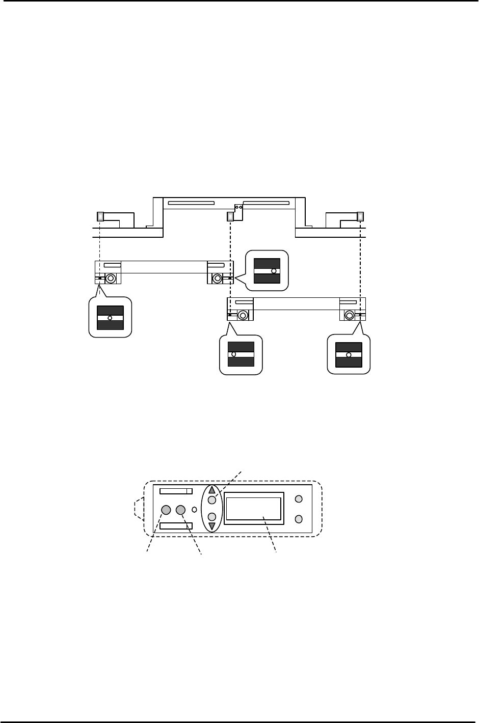
5.15 Moveable Rail Engagement Check Sensor Adjustment
1. Ensure the silver stickers on the main table are clean.
2. Ensure the sensor lenses are clean and free of obstructions.
3. Set the main table at either the IN or Out loading position.
4. Manually, raise the Z– axis to engage with either the IN or OUT carrier.
(Check that the sensor beam is centered on the silver sticker)
(If not centered, use the adjusting bolts to center the sensor heads accordingly)
5. Set the main table at the Z origin position. (Z0) at either the IN or OUT loading position.
6. To unlock the sensor, press the up & mode keys simultaneously for more than 3 seconds.
7. Set the sensor to the “A” mode by pressing the mode and up keys quickly.
8. Set the sensor to 110P via the up/down keys, when the beam is centered over the silver
sticker. (110P indicates a percentage)
9. Jog the table in the Y- direction to find both edges of the silver sticker. (Record the pulse
count at each edge.) The sensor display will change from Red to Green. (Red = ON,
Green = OFF)
(Centered)
(To the left)
(To the right)
Moveable
rail
engagement check
sensor 1
Moveable
rail
engagement check
sensor 3
Moveable
rail
engagement check
sensor 2
IN Loading Position
OUT loading Position
(Centered)
Figure 20
MODE
SET
100P
CH
A
A B
Sensitivity key
Output A display
Output B display
Digital display
Figure 21

FK-9F98-05 CP-643E Training Text for Service Engineers
Edition 5.0 Chapter 5. Loader and Conveyor Adjustment [13/28]
Fuji Machine Mfg. Co., Ltd. Okazaki
SMT Equipment Quality Assurance Dept.
Technical Support Div. Section No.2
5-
13
10. Divide the total pulse count found in step 8, by half. The result should be around the
center of the silver sticker and close to the YL pulse count. (Check the YL proper data) If
not, adjust the sensor head position accordingly. (Balance is the key point)
11. Set the Z- axis to the minus stopper position and set the sensor to the B mode, by pressing
the mode and up keys quickly. Using the “B” mode, set the sensor sensitivity to 100P.
12. Return to the “A” mode and check the sensor performance while raising and lowering the main
table. If problems exist, repeat the procedure outlined above.
13. Lock the sensor settings by pressing both the up and mode keys simultaneously for more than
3 seconds.
<I/O → Standard → IN>
X0C0 Adjusting Rail Engagement Check IN
X0DB Adjusting Rail Engagement Check OUT
X0DC Adjusting Rail Engagement Check Center
Hints For Adjusting the Moveable Rail Engagement Check Sensors
1. First clean the sensor target stickers, as any dirt, grease or dust will effect the sensor readings.
2. Always engage with the carrier first then descend and calculate the center position. Failure to do this
will result in erroneous results.
3. If the beam is in the center of the silver target when engaged with the rail, but is off center when the
table descends to Z0, then the sensor bracket is tilted. In this case calculate where the center is at
Z0. Is it more positive or more negative in relation to YL?
If the center at Z0 is more negative in relation to YL then the sensor is tilted towards the front of the
machine. In this case tilt it in the opposite direction a little using the play in the bracket.
Having done this ascend the XY tablet to engage with the carrier and use the forward/backward
adjusting bolt to reposition the sensor beam in the center of the sticker.
If the center at Z0 is more positive in relation to YL then the sensor is tilted towards the back of the
machine. In this case tilt it in the opposite direction a little, using the play in the bracket.
Having done this ascend the XY tablet to engage with the carrier and use the forward/backward
adjusting bolt to reposition the sensor beam in the center of the sticker.