CP643E.pdf - 第72页
FK-9F98-05 CP- 643E Training Text for Service Engineers Edition 5.0 Chapter 5. Loader and Conveyor Adjustment [ 9 / 28 ] Fuji Machine Mfg. Co., Ltd. Okazaki SMT Equipment Quality Assurance Dept. Technical Support Div. Se…
FK-9F98-05 CP-643E Training Text for Service Engineers
Edition 5.0 Chapter 5. Loader and Conveyor Adjustment [8/28]
Fuji Machine Mfg. Co., Ltd. Okazaki
SMT Equipment Quality Assurance Dept.
Technical Support Div. Section No.2
5-
8
5.11 In / Out Loading Position (Z– Axis)
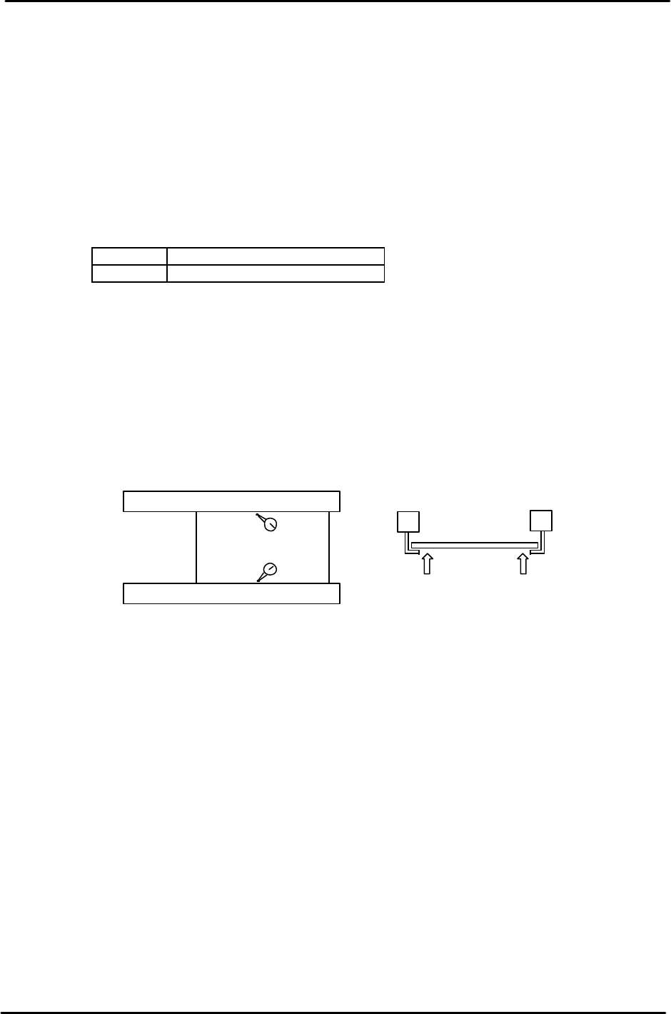
1. Clamp a board on the main conveyor and move the table to the OUT loading position.
2. Manually, advance the OUT carrier to the forward end and open the carrier claws.
3. Raise the Z-axis manually to a position where the PCB can be clamped by the carrier
claws. (If the claw interferes with the PCB, open the carrier claws and raise the Z-axis a
little more.)
4. Open the main conveyor clamp by I/O.
<I/O → Standard → IN>
Y043 X Y - Table Panel CLAMP
Y044 X Y - Table Panel UNCLAMP
5. Lower the Z-axis just until it is clear from the PCB held by the carrier.
6. Set a dial indicator on the PCB close to the carrier claw on the reference side. Manually
raise the Z-axis again until the PCB lifts 0.5mm. Note the servo counter of the Z-axis.
7. Check the servo counter at a position close to the carrier claw on the secondary side.
Compare the two counter values. The higher value is called ZL_OUT. As for ZL-IN,
calibrate the IN loading position in the same manner.
8. When the Z load position has been determined, set the Z axis at the servo count position
and enter it into proper at the host PC.
Note:
The highest value for both the IN and Out Z loading positions is referred to as ZL upper.
The lowest value for both the IN and Out Z loading positions is referred to as ZL lower.
ZL upper and lower pulse counts are used as references for setting sensor positions in the
next section.
Carrier (Moveable Rail)
Carrier (Fixed Rail)
Z pushes the Pcb up 0.5mm
from the carrier claws
Figure 15
FK-9F98-05 CP-643E Training Text for Service Engineers
Edition 5.0 Chapter 5. Loader and Conveyor Adjustment [9/28]
Fuji Machine Mfg. Co., Ltd. Okazaki
SMT Equipment Quality Assurance Dept.
Technical Support Div. Section No.2
5-
9
5.12 Z-axis Mechanical Valve Adjustment
1. Adjust the mechanical valve and dog for the moveable rail locking cylinders as follows.
The moveable rail on the main table should lock when the Z-axis is positioned at;
[ZL lower – 650 +/- 50 pulses.]
2. If out of range, move the dog up or down until the rail clamps within the specified range.
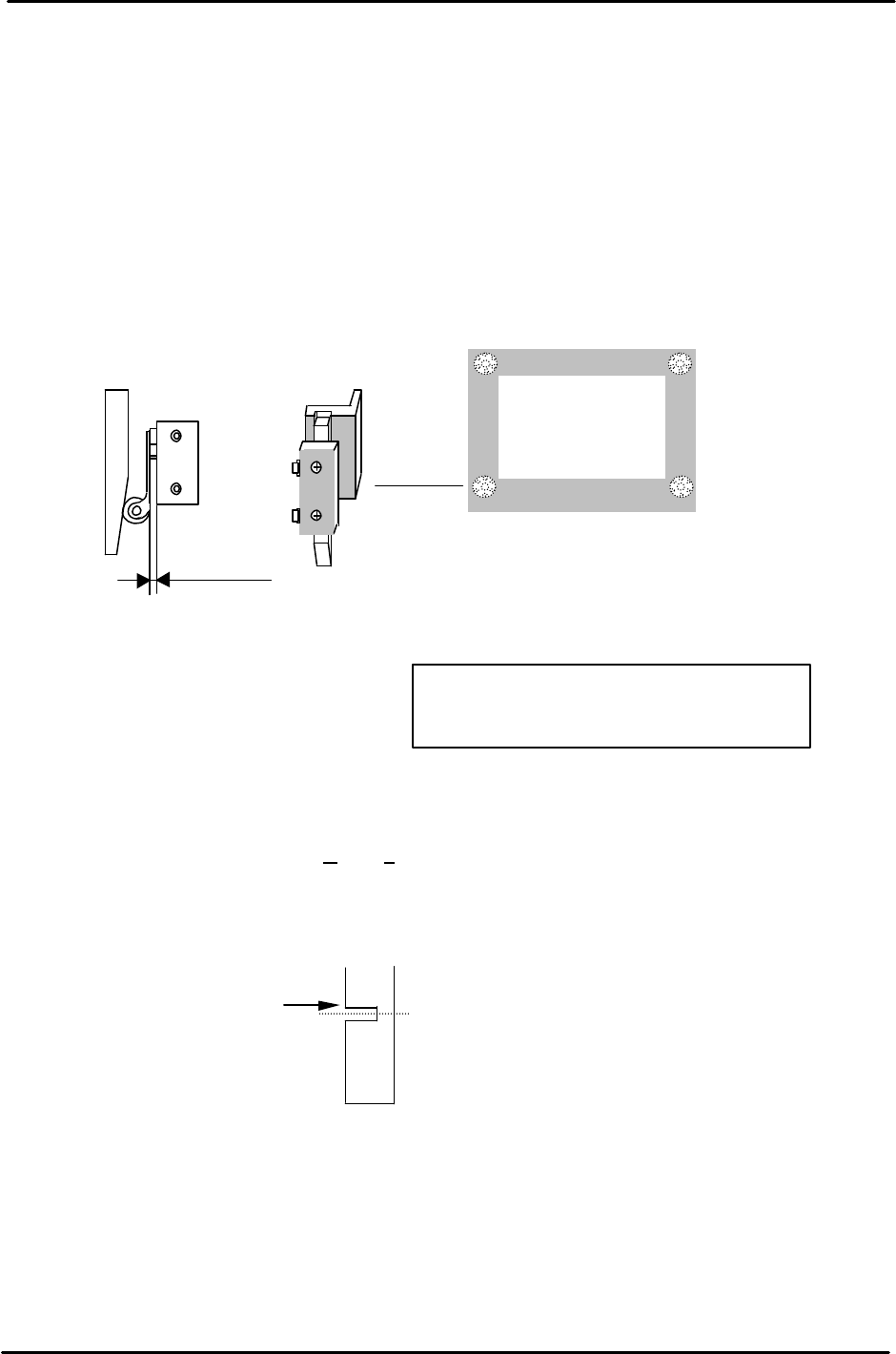
3. After adjustment, make sure the pneumatic swich lever has 1 to 2mm of play. Too much pressure
on the lever will result in damage to the pneumatic switch.
5.13 Z-axis Sensor Adjustment
1. Set the Upper End Sensor 2 flag (Fig. 17) at [ Z0 + 2300 ± 50pls.]
(Standard I/O: X065 M-LFTR UP2)
2. Set the Upper End Sensor 1 (Middle Load Position) flag (Fig. 17) at
[ ZL (Lower) – 10500 – 125 ± 50pls.]
(Standard I/O: X064 M-LFTR UP1)
3. Calculate the Middle Loading Position (Proper Data) as follows:
CP-643E [ML= ZL Lower – 10500 ± 50pls.]
Note: this is a proper data item for the Middle Load Pos., once calculated, enter it into proper at
the host PC.
4. Set the Downward End Sensor flag (Fig. 18) at [Z0 + 400 ± 50pls.]
(Standard I/O: X067 M-LFTR DWN END)
1
to
2mm
play
Figure 16
Move the flag to trigger
the sensor at this edge.
Middle Load Position
Figure 17
Remove the MOT flag to allow adjustment
for all other sensors first. Adjust the MOT
last.
FK-9F98-05 CP-643E Training Text for Service Engineers
Edition 5.0 Chapter 5. Loader and Conveyor Adjustment [10/28]
Fuji Machine Mfg. Co., Ltd. Okazaki
SMT Equipment Quality Assurance Dept.
Technical Support Div. Section No.2
5-
10
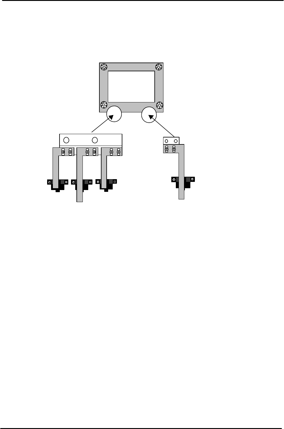
5. Set the MOT sensor flag (Fig. 17) at [ Z0 +150 ± 50pls.]
(Standard I/O: X066 M-LFTR )
6. Ensure the flags are centered within the sensors after adjustment.
Upward end sensor 2
Upward end sensor 1
Downward end sensor
MOT Sensor
Figure 18