CP643E.pdf - 第110页
FK-9F98- 05 CP- 643E Training Text for Service Engineers Edition 5.0 Chapter 7. Camera Adjustment [ 5 / 10] Fuji Machine Mfg. Co., Ltd. Okazaki SMT Equipment Quality Assurance Dept. Technical Support Div. Section No.2 7-…
FK-9F98-05 CP-643E Training Text for Service Engineers
Edition 5.0 Chapter 7. Camera Adjustment [4/10]
Fuji Machine Mfg. Co., Ltd. Okazaki
SMT Equipment Quality Assurance Dept.
Technical Support Div. Section No.2
7-4
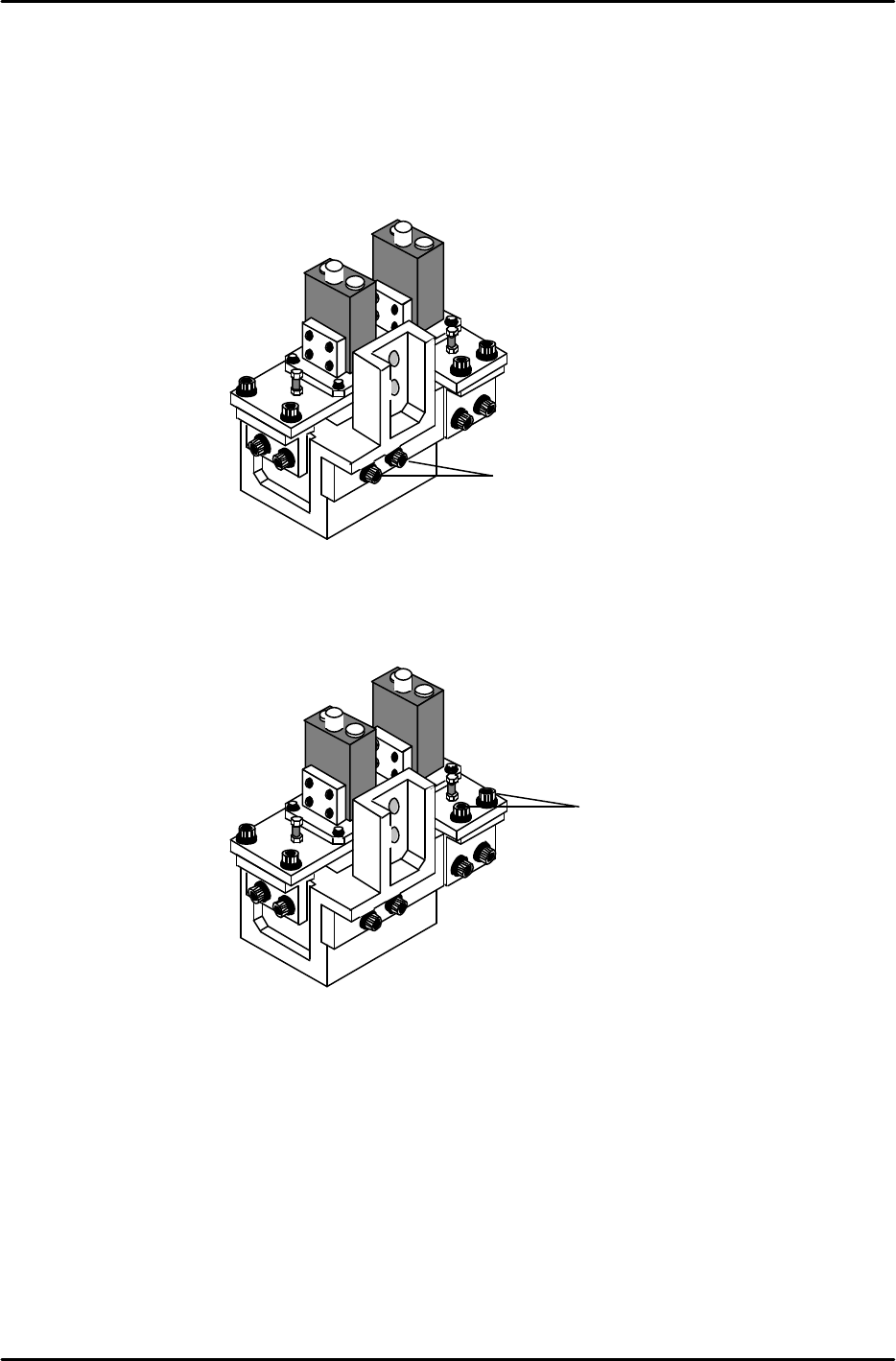
6. As the narrow camera bracket is attached to the wide camera bracket, it is necessary to adjust the
wide camera bracket first when adjusting both cameras. Performing narrow camera adjustments
first will necessitate the adjustment being performed twice.
7. To adjust the narrow camera in the Y-direction, loosen the Y-axis positioning bolts (Item 1 in figure 9)
and adjust the camera position accordingly. Once the adjustment is complete, tighten the bolts with
the required amount of torque (13Nm).
8. To adjust the narrow camera in the X-direction, loosen the X-axis positioning bolts (Item 1 in figure
10) and adjust the camera position accordingly. Once the adjustment is complete tighten the bolts
with the required amount of torque (8Nm).
Rear View
Figure 9
1
Rear View
Figure 10
1
FK-9F98-05 CP-643E Training Text for Service Engineers
Edition 5.0 Chapter 7. Camera Adjustment [5/10]
Fuji Machine Mfg. Co., Ltd. Okazaki
SMT Equipment Quality Assurance Dept.
Technical Support Div. Section No.2
7-5
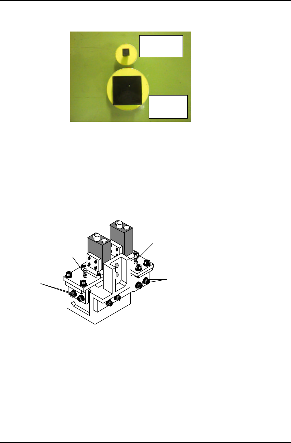
7.4 Focus Adjustments
1. Before proceeding to set the focus, ensure the cameras (nozzle images) are centered.
2. Place the wide camera inspection jig on head A and bring it to the 6
th
station at 200 degrees.
3. Display the wide camera monitor using the following commands:
[SET] → [MANUAL] → [VISION] → [ADJUST] → [GET ACQ] → [GET ACQ] → [CHANGE] →
(SELECT CAMERA) → [DISPLAY]
4. Adjust the focus of the wide camera by loosening the two positioning bolts (1) and use the focus
adjustment bolt (2) to raise or lower the camera (see figure 12).
5. The camera is focused when the wide camera monitor shows a clear, sharp image of the wide
camera inspection jig.
6. Once the adjustment is complete, tighten the bolts with the required amount of torque (13Nm).
7. Adjust the focus of the narrow camera by loosening the two positioning bolts (3) and use the focus
adjustment bolt (4) to raise or lower the camera (see figure 12).
8. When both adjustments are finished set the gap between the lens cover and the prism box to 0.5mm.
Narrow camera
inspection jig
Wide camera
inspection jig
Figure 11
Rear View
Figure 12
1
2
3
4
FK-9F98-05 CP-643E Training Text for Service Engineers
Edition 5.0 Chapter 7. Camera Adjustment [6/10]
Fuji Machine Mfg. Co., Ltd. Okazaki
SMT Equipment Quality Assurance Dept.
Technical Support Div. Section No.2
7-6
7.5 Wide / Narrow Camera Skew and Resolution Adjustment
1. The camera skew adjustment is performed in order to align the camera with the X- and the Y- axes.
This is vital for determining accurate angular compensation at station 10 (FQ).
2. The camera resolution indicates the size of a pixel in the X and the Y direction. If the camera
resolution lies outside the specified range, the dimensions of the component inspected will not match
the data contained in the part data, and a vision processing error will occur.
3. Turn the 11
th
station (Y029) and 10
th
station solenoid valves OFF (Y031) with the cam at 0 degrees.
4. Put the wide camera inspection jig on Head A, nozzle No.1.
5. Inch the jig to the 11
th
station and set the cam at 200 degrees.
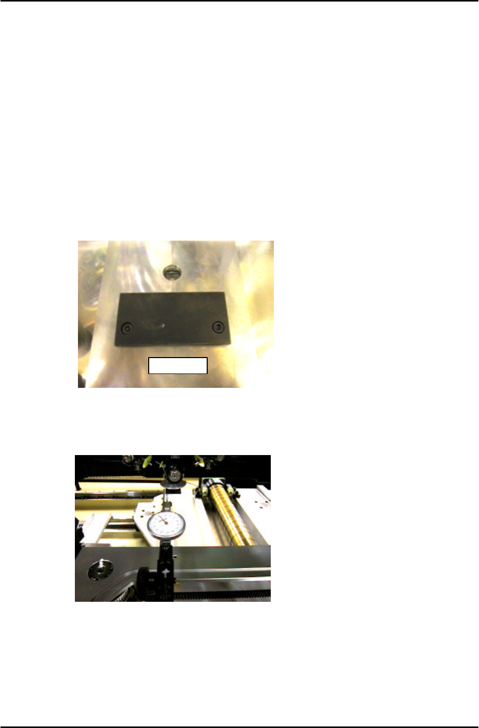
7. Remove the back up plates and attach the “XY Slide (magnet stand)” to the XY table, see Figure 13:
8. Set the dial gauge stand on the magnet stand and set the dial gauge tip to the horizontal flat edge of
the jig, see figure 14:
9. Set the X-axis inching speed to 1% and then inch the dial gauge tip from right to left across the
horizontal flat edge of the jig. Rotate the shaft until the dial gauge shows that the jig is parallel to the
X-axis. (Tol: 0 +/- 0.01mm)
10. Remove the dial gauge and inch the C-axis until the angle is 0 degrees and the jig is half way
between the 11
th
and 12
th
stations.
DCPJ0670
Figure 13
Figure 14