CP643E.pdf - 第60页
FK-9F98-05 CP- 643E Training Text for Service Engineers Edition 5.0 Chapter 4. Station Adjustment [ 15 /18] Fuji Machine Mfg. Co., Ltd. Okazaki SMT Equipment Quality Assurance Dept. Technical Support Div. Section No.2 4-…
FK-9F98-05 CP-643E Training Text for Service Engineers
Edition 5.0 Chapter 4. Station Adjustment [14/18]
Fuji Machine Mfg. Co., Ltd. Okazaki
SMT Equipment Quality Assurance Dept.
Technical Support Div. Section No.2
4-
14
Waste tape cutter unit positioning check
1. Move the table 1875 pulses from the servo counter value of “D1” position.
2. Set a feeder to device number 1. Rotate the index and ensure that the waste tape is cut
completely by the cutter.
3. Check device number 3 at the same position.
4. If difficult, move the unit right and left.
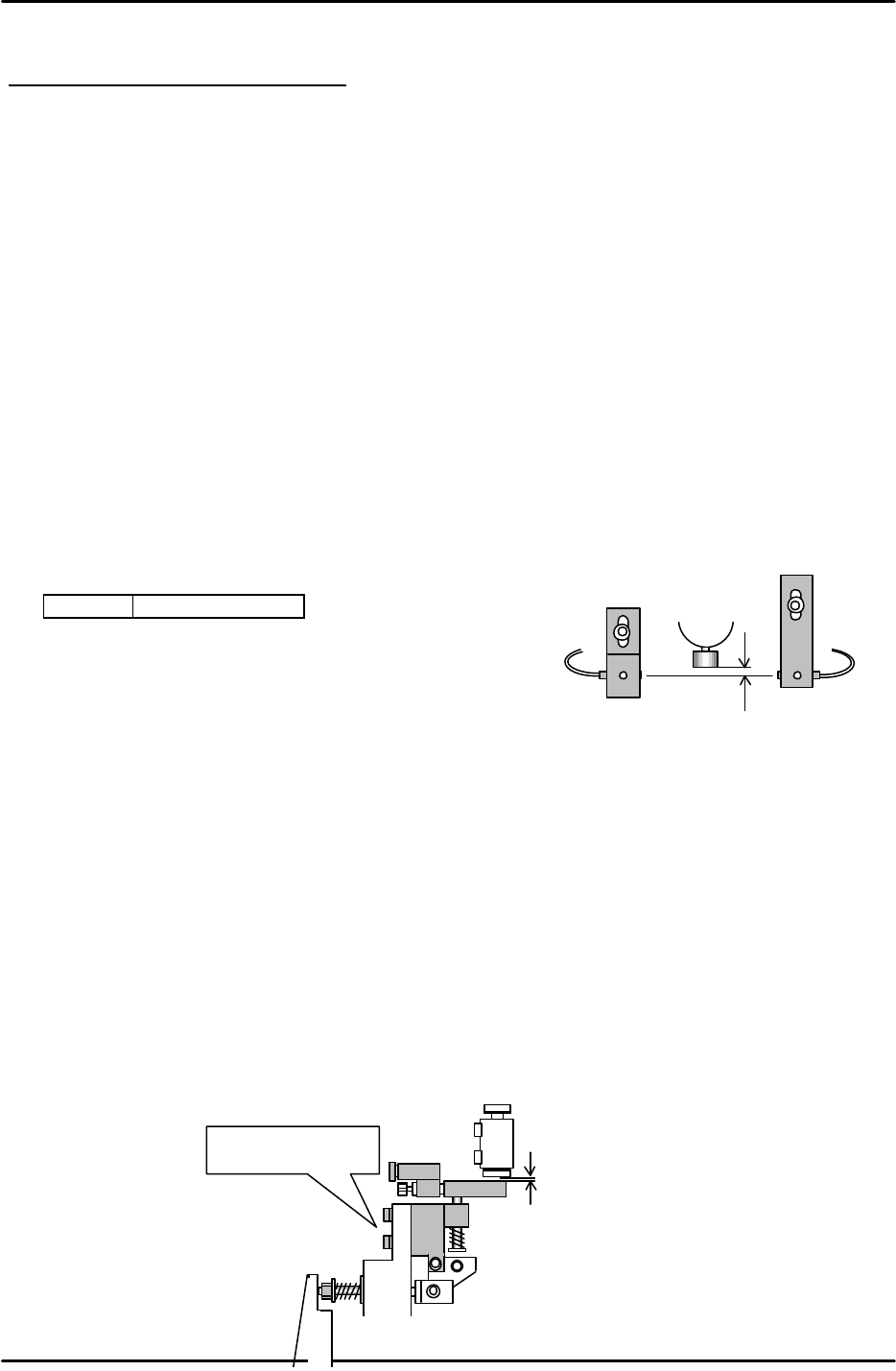
4.15 Station 2 Large Parts Check Adjustment
1. Set the nozzle jig (Jig No.: 71615WPJ0082) to the nozzle holder. Set the cam angle to 200
degrees, and align the sensor bracket.
2. Adjust the sensor so the light beam passes through 0.7 to 0.8mm below the tip of the nozzle.
3. As for the amplifier volume, turn ON the green LED and rotate 1 scale further.
<I/O à Standard I/O à IN>
X043 L PICKUP CHK
4.16 Station 16 Part Eject Adjustment
1. Move the reference shaft, (with the lowest spool) to station 16.
2. When the cam angle to set to 203 degrees, the shaft is pressed and the spool is raised by the
lever.
3. Adjust the clearance between the pushed up spool and the lever to 0.05 to 0.10mm.
4. As for the lever position, align the lever hole with the mechanical valve hole.
5. Ensure that the clearance between the lever and the valve is NOT zero. Check all shaft spools.
6. Open the speed controller 4.5 revolutions away from the fully closed position.
0.7 to 0.8mm
0.05~ 0.1mm
Adjustment bolts.
Figure 31
Figure 32
FK-9F98-05 CP-643E Training Text for Service Engineers
Edition 5.0 Chapter 4. Station Adjustment [15/18]
Fuji Machine Mfg. Co., Ltd. Okazaki
SMT Equipment Quality Assurance Dept.
Technical Support Div. Section No.2
4-
15
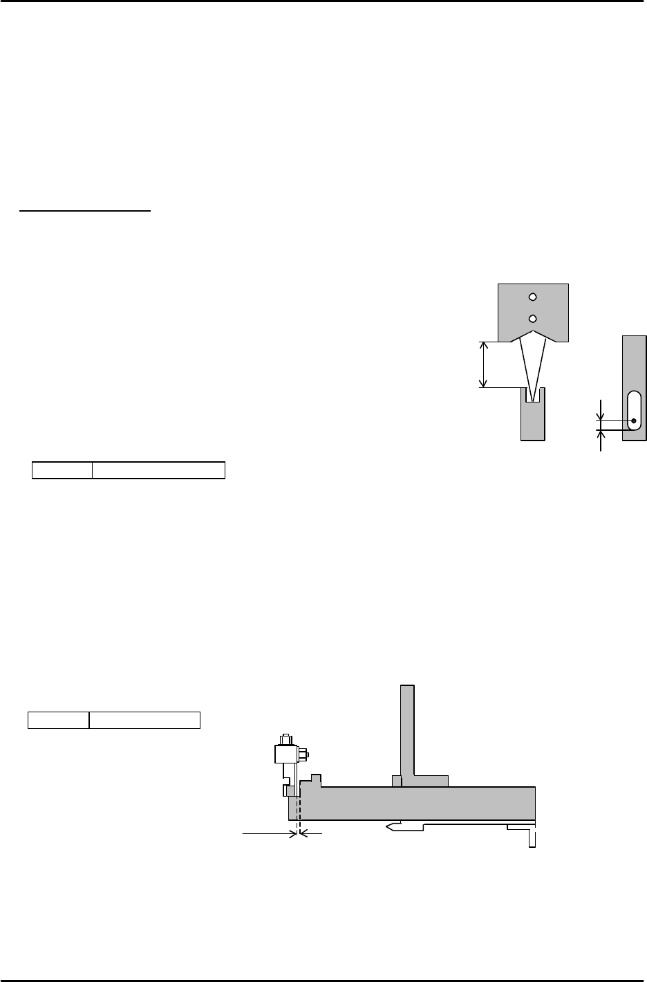
4.17 Tape-End Detection
1. Set a feeder at slot 1 (D1) and zero set the m/c.
2. Move the device table to the pick up position, “PICK UP POS. T1”
3. Adjust the clearance between the top of the feeder and the sensor at 11 to 12 mm. Adjust the
oval hole of the bracket so that the beam direction, front-rear, is positioned 2.5mm away from the
back of the cut out.
[Amplifier adjustment]
1. Rotate the sensitivity trimmer slowly from “ MAX” to “ MIN” and ensure that the sensor turns ON
at around the center of the scale.(Tape end) Rotate another 0.5 to 1 scale from this position.
2. Set the scale on the feeder and ensure that the sensor turns OFF.
3. Prepare a 3mm thick component. Set it on the feeder and
ensure that the sensor turns OFF.
4. Move the table and check if the light beam is positioned
in the center of the feeder cut out. Check this using the servo counter.
5. Confirm sensor reaction by I/O.
<I/O à Standard I/O à IN>
X042 TAPE END CHK
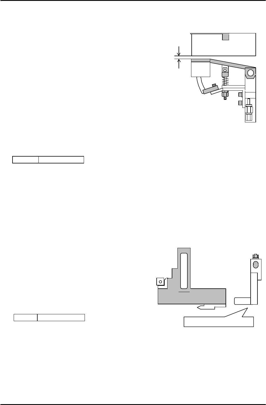
4.18 Feeder, Tape Retainer, Up Prevention Sensor Adjustment
1. Align the sensor bracket using the jig or feeder.
2. Set the clearance between the jig and sensor bracket to 0.5mm as indicated in figure 34.
3. As for the height, the sensor bracket should just clear the jig.
4. Confirm sensor reaction by I/O.
<I/O à Standard I/O à IN>
X02D FEEDER CHK
2.5mm
11 to 12mm
Figure 33
0.5mm
Jig Z9913AWPJ9310
Figure 34
FK-9F98-05 CP-643E Training Text for Service Engineers
Edition 5.0 Chapter 4. Station Adjustment [16/18]
Fuji Machine Mfg. Co., Ltd. Okazaki
SMT Equipment Quality Assurance Dept.
Technical Support Div. Section No.2
4-
16
0.2mm
Feeder
4.19 Feeder Up Prevention Sensor Adjustment
1. Fix the stopper bracket in the center of the oval-shaped hole.
2. Adjust the stopper nut, so that the bottom of the feeder is
parallel to the plate surface in the forward front-rear directions.
3. Check the plate height in the right-left direction.
Move the feeder to the highest position. Adjust the bracket so the
clearance between the surface of the plate and the feeder is 0.2mm.
4. Adjust the sensor bracket so that the sensor turns ON when the
plate is lowered 0.5mm using a feeler gauge and OFF using a 0.7mm feeler gauge.
(The Sensor should NOT turn ON when the plate is pressed down by a 0.7mm feeler
gauge.)
5. Confirm sensor reaction by I/O.
<I/O à Standard I/O à IN>
X02D FEEDER CHK
4.20 Interference Prevention Sensor Adjustment at Station 18
1. Confirm the tilt of the L-type lever.
2. Align the vertical, front and rear directions
of the sensor bracket using a jig.
3. Raise the sensor gradually from the bottom.
The LED of the sensor turns ON, and then turns
OFF. Turn another 0.5mm from the OFF position
and fix the sensor.
4. Confirm sensor reaction by I/O.
<I/O à Standard I/O à IN>
X037 FEEDER 18ST
Check bottom regarding tilt.
Figure 35
Figure 36