CP643E.pdf - 第36页
FK-9F98-05 CP-643E Training Text for Service Engineers Edition 5.0 Chapter 3. X, Y, Z and D-axes Adjustment [ 17 /26] Fuji Machine Mfg. Co., Ltd. Okazaki SMT Equipment Quality Assurance Dept. Technical Support Div. Secti…
FK-9F98-05 CP-643E Training Text for Service Engineers
Edition 5.0 Chapter 3. X, Y, Z and D-axes Adjustment [16/26]
Fuji Machine Mfg. Co., Ltd. Okazaki
SMT Equipment Quality Assurance Dept.
Technical Support Div. Section No.2
3-16
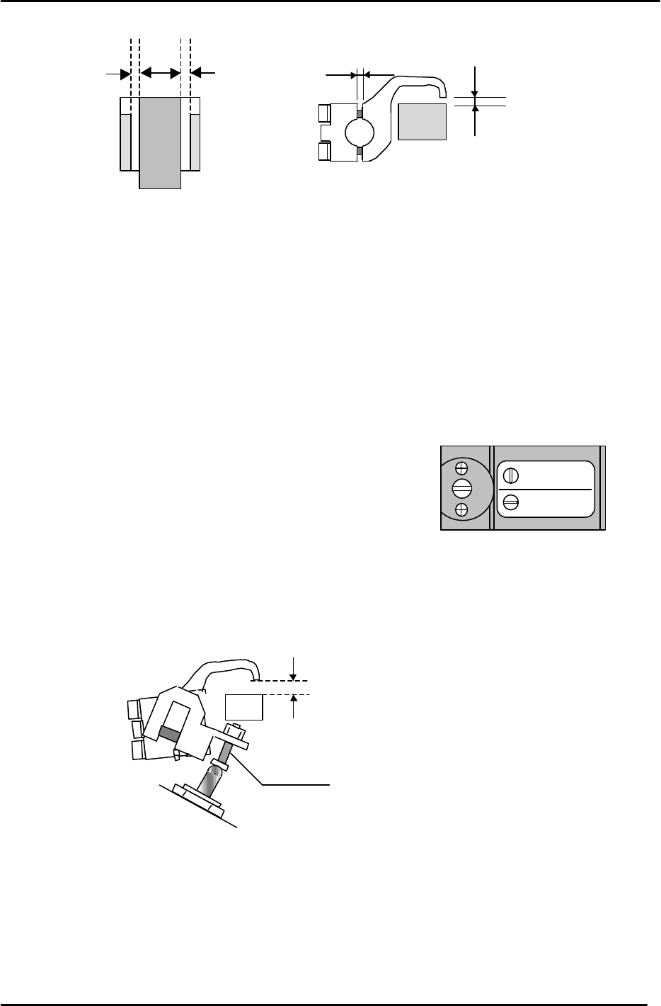
6. Proceed to lock each claw making sure that the clearance values are within the ranges shown
above. It may be useful to lock the two center claws and the two claws at both ends of the rail first,
then proceed to lock the claws in between. Remember that clearance between the tip of the claw
and the guide rail should be in the range 0.03 to 0.10 mm. The claw is attached to the rail by two
3mm bolts. Tightening the top bolt will increase the clearance, tightening the bottom bolt will
decrease the clearance.
3.13.2 (Part 2) Claw Float Adjustment
1. Set the reference pin switch valve to “Pin Ref”.
2. Place a 4mm thick PCB in the main conveyor clamper.
3. Activate but do not lock the adjustable rail clamping solenoid.
4. At this position, there should be 0.5mm clearance between the clamper claw tips and the PCB.
5. Use the adjusting bolt on the claw float cylinder to set the clearance at 0.5mm. Note that the
clearance will vary slightly at different points on the clamper rail. Set the 0.5mm clearance at the
narrowest point.
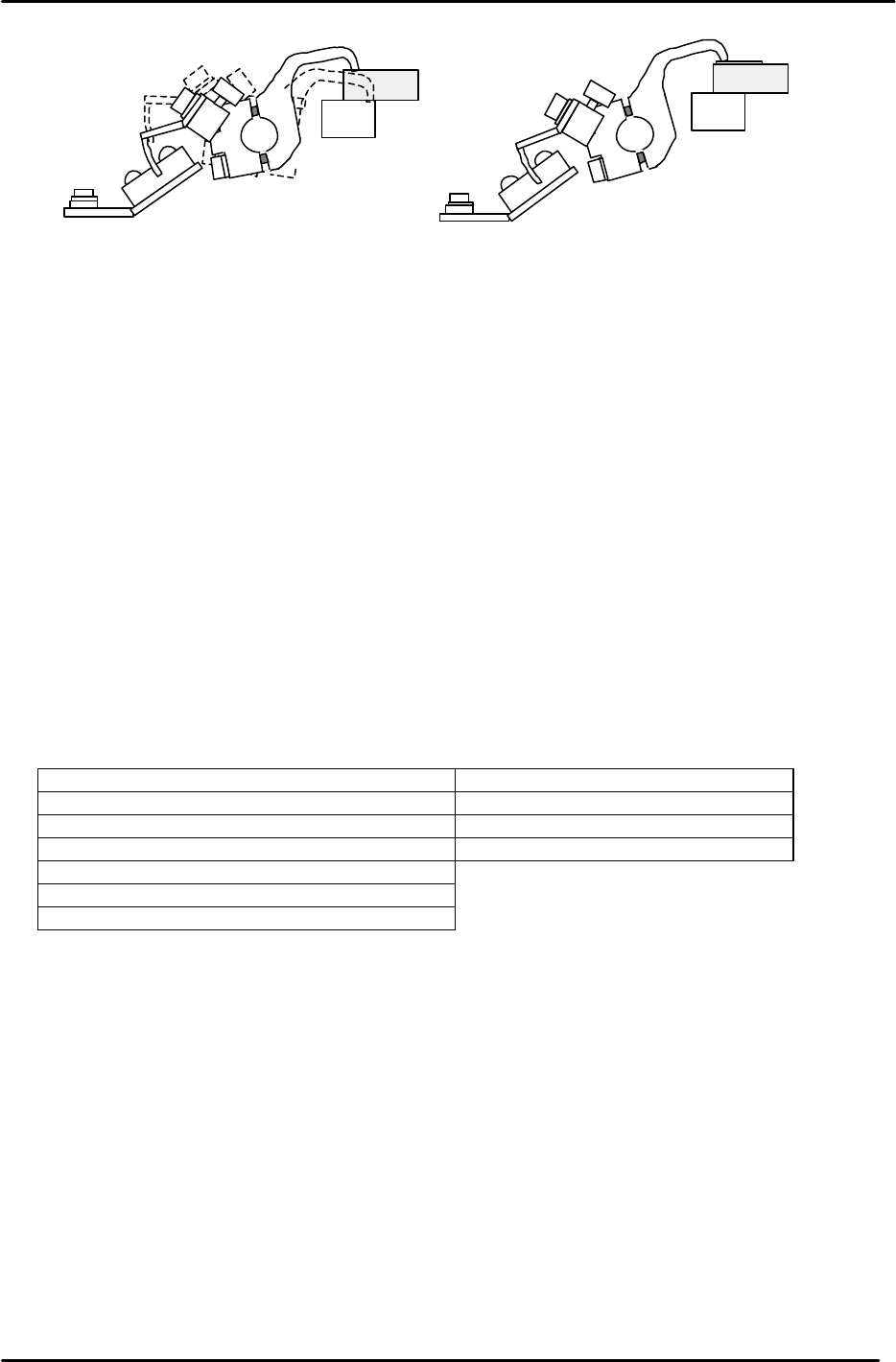
6. On the fixed rail side, set the position of the clamping claw float sensor flag so that the sensor LED
is OFF when a 4mm thick PCB is clamped and ON when a 4.5mm PCB is clamped. Note that the
clamping solenoid should be activated but not locked for this adjustment. I.e. In this case “clamped”
means press the clamping solenoid once but do not lock it. Note: the sensor is Dark-On so when the
LED is Off the I/O input is ON, and vice versa. I/O: (X032 PCB Set CLP OK).
* Note that 0.5mm clearance on both sides is the ideal. However, this may be difficult to
achieve. In such cases a rough balance between the two is acceptable.
0.5mm0.5mm *
0.03 to 0.10 mm
(A)
0.9 mm
Figure 25
Mark Ref.
Pin Ref.
Figure 26
4.5mm
Adjustment Bolt
Figure 27
FK-9F98-05 CP-643E Training Text for Service Engineers
Edition 5.0 Chapter 3. X, Y, Z and D-axes Adjustment [17/26]
Fuji Machine Mfg. Co., Ltd. Okazaki
SMT Equipment Quality Assurance Dept.
Technical Support Div. Section No.2
3-17
3.13.3 (Part Three) Clamping Cylinder Sensor Adjustment
1. Check that PCBs in the range of 0.5mm to 4.0mm can be clamped smoothly.
2. There are three clamping cylinders and two sensors on each cylinder. On each cylinder, the upper
sensor is the CLAMP CHECK sensor, and the lower sensor is the UNCLAMP CHECK sensor.
3. For the UNCLAMP CHECK sensors, open the rail to its unclamp limit. At this position find the point
where the sensor LED turns ON then move it 0.5mm further toward the ON direction.
4. For the CLAMP CHECK sensors, set the sensor so that it is ON when a 4.0mm board is clamped
and OFF when a 5.0mm board is clamped. Note that the clamping solenoid should be activated but
not locked for this adjustment. I.e. In this case, “clamped” means press the clamping solenoid once
but do not lock it.
5. Finally confirm that the CLAMP CHECK SENSORS are ON when the clamper rail is clamped with
no PCB in place.
6. Check the Clamping Cylinder Sensor and Valve reaction in I/O.
<I/O à Standard I/O à (IN or OUT) >
IN X060 M-LFT CLAMP RF OUT Y050 M-LFT CLAMP F
IN X061 M-LFT CLAMP RR OUT X051 M-LFT UNCLAMP F
IN X062 M-LFT UNCLAMP RF OUT X056 M-LFT CLAMP R
IN X063 M-LFT UCLMP RR OUT X057 M-LFT UNCLAMP R
IN X06C M-LFT CLAMP LF
IN X06D M-LFT UCLMP LF
IN X032 PCB SET CLP OK
Figure 28
4.0mm PCB Clamped
(Sensor LED OFF)
4.5mm PCB Clamped
(Sensor LED ON)
FK-9F98-05 CP-643E Training Text for Service Engineers
Edition 5.0 Chapter 3. X, Y, Z and D-axes Adjustment [18/26]
Fuji Machine Mfg. Co., Ltd. Okazaki
SMT Equipment Quality Assurance Dept.
Technical Support Div. Section No.2
3-18
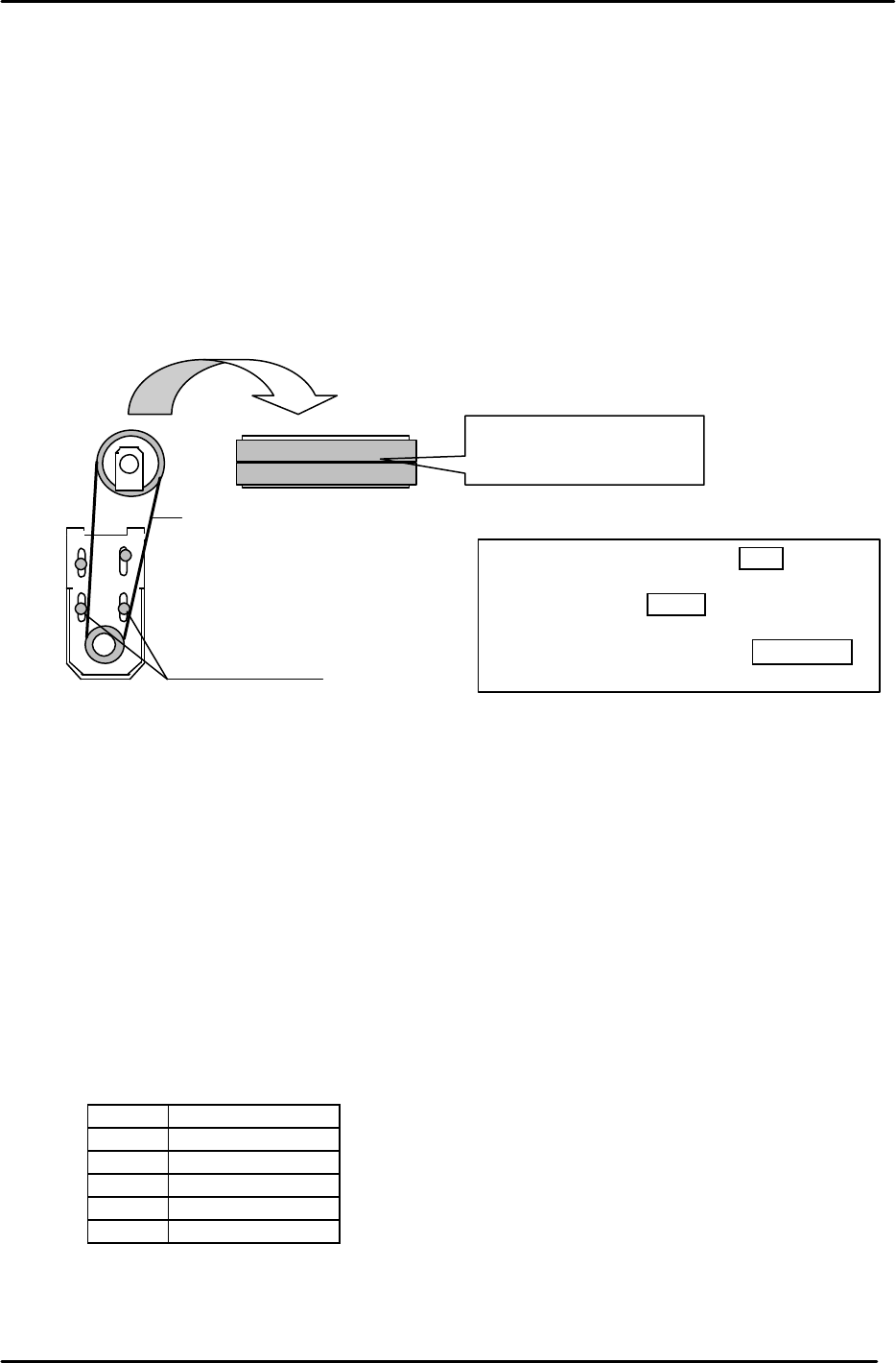
3.14 D-axis Zero Setting (0.00853mm/pulse)
1. Remove the minus OT flags on D1/D2 and the timing belts from the D-axis.
2. In Mecha-check mode, complete zero setting by blocking the zero set sensor with a scale.
3. Set the D1 (2) axis counter value to - 3750 pulses.
4. Place the D1 table against the plus mechanical-stopper, (D2 minus mechanical stopper) and
attach the timing belts. (One tooth on the belt changes the value about 127 pulses)
Tolerance: - 3750±100 pulse
Ensure the markings on the belt are aligned and facing out when attaching.
5. Check that the final servo counter value at the stopper is - 3750 ± 100 pulses.
6. Adjust the OT flags to turn the minus over travel sensors ON at 1407 pulses away from the
mechanical-stoppers.
7. Move the table to the 2500 pulse position. Adjust the flag to turn the D1 (D2) zero set sensor
ON at this position. Make sure the timing belts remain in the center of the pulley when the
device table is jogged.
8. Set the travel limits according to the illustrations in figure 30 (D1) and 31 (D2). Enter the
values to the proper at the host PC.
9. Check the sensor reaction in I/O.
< I/O à ETC à Servo board 3 à IN
SX004 D1 AXIS +OT
SX008 D2 AXIS +OT
SX005 D1 AXIS - OT
SX009 D2 AXIS - OT
SX006 D1 AXIS ZERO
SX00A D2 AXIS ZERO
Torque = 120Nm
.
Timing belts
274 J 012
274 J 013
274 J 014
Numbers in sequence
and facing out.
Figure 29
D1-axis timing belt tension
=
5
2
±
5
D2-axis tension = 49.5±5
D-axis motor bracket torque = 1200kgf.cm