CP643E.pdf - 第121页
FK-9F98- 05 CP-643E Training Text for Service Engineers Edition 5.0 Chapter 8. Placement [ 6 / 6] Fuji Machine Mfg. Co., Ltd. Okazaki SMT Equipment Quality Assuranc e Dept. Technical Support Div. Section No.2 8 - 6 8.2 P…
FK-9F98-05 CP-643E Training Text for Service Engineers
Edition 5.0 Chapter 8. Placement [5/6]
Fuji Machine Mfg. Co., Ltd. Okazaki
SMT Equipment Quality Assurance Dept.
Technical Support Div. Section No.2
8
-
5
17. After the target results are obtained, press the following keys to check all measurement data.
Note: If the Avg.d?(1/1000 degree) is over ±200, check the parallelism of the “5st original position”
and “10st” again.
18. The factory tolerance values are as follows:
? X, ?Y (1/1000mm) 3 dX?3dY (1/1000mm)
less than ±20 less than 80
? Q (1/1000deg) 3 dQ (1/1000Deg)
less than ±200 less than 990
Max and Min dX, dY, (1/1000mm)
less than ± 80
Note: The factory tolerance values listed here are for new machines. Results may differ
depending on the condition of older machines.
19. After completing PAM, receive the proper to the host computer. Then, take the Proper X, Y placing
offset values measured for nozzle 1 and input the same figures to nozzles 2 to 6.
20. Turn OFF the machine and re-install the machine ROM card. Then reset-start and transmit the
proper, status and programs.
21. Procedure completed.
CP_6.PAM.PROGRAM
Prod 00000 Sche 00000
V1.01
off line
Print
Return
Page141
XY
C
jog
000000000000000
000000000000000
Measurement Result
Avg. dX Avg. dY Avg.dQ Nozzle Type
-4 -2 -98 All Nozzle
All degrees
Max. dX Max. dY Max. dQ All data
26 19 476 5000
Min. dX Min. dY Min. dQ dXdY
-13 -9 -278 [1/1000mm]
3sig.X 3sig.Y 3sig.Q dQ
-18 4 483 [1/1000deg]
Operation: Front
Ready
Size
Data Display
Figure 6
FK-9F98-05 CP-643E Training Text for Service Engineers
Edition 5.0 Chapter 8. Placement [6/6]
Fuji Machine Mfg. Co., Ltd. Okazaki
SMT Equipment Quality Assurance Dept.
Technical Support Div. Section No.2
8
-
6
8.2 Placing Accuracy Check using the FUJI 96 Board
[PCB] FUJI96
[Program] 96MC63
96PC63
[Nozzles] f 1.0 f 1.3 f 2.5 f 5.0
[Parts] 1005C, 1608C, 2125R, 3216R, MINR (L), SOIC28PIN
[Double sided tape]
1. Run the above program and check the component placement accuracy on the FUJI 96
board, (using fiducial marks), using a digitizer.
2. Placing accuracy tolerances
When using MARK X Y : less than ±0.08
When using PIN X Y : less than ±0.15
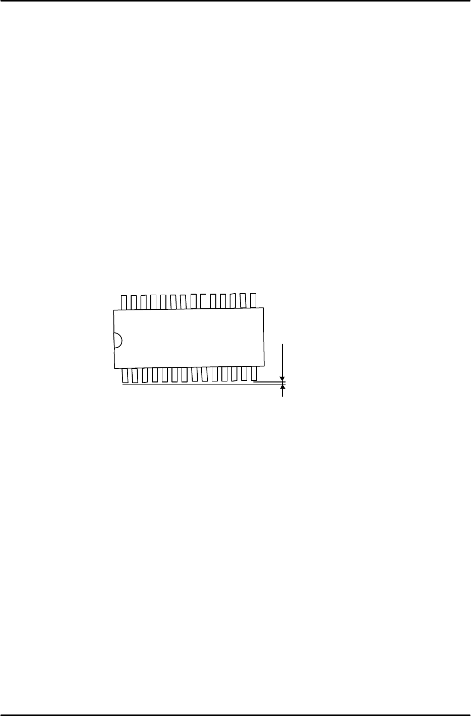
Placing accuracy for the SOIC (checking skew)
(When using MARK) X Y : less than ±0.08
Q : refer to the illustration below.
3. Check the following when the accuracy is out of range:
a. Repeat the Nozzle Center Test (include all nozzles)
b. For theta inaccuracies, check and adjust the Origin Position of station 5.
Check and adjust the 10
th
station (FQ) proper data.
Less than 0.05

FK-9F98-05 CP-643E Training Text for Service Engineers
Edition 5.0 Chapter 9, Miscellaneous Adjustments [1/2]
Fuji Machine Mfg. Co., Ltd. Okazaki
SMT Equipment Quality Assurance Dept.
Technical Support Div. Section No.2
9-1
Chapter 9 Miscellaneous Adjustments
9.1 Backup pin Adjustment
1. Set the height of the Backup pins as specified below.
CP-643E Backup pin 39.2 +/-0.05mm
Clamp the Fuji096 PCB to the table, check for any gaps between the bottom surface of the PCB
and the top of the pin.
Note: Check the backup pin height close to the reference and movable rails. (The middle part of
the board may be warped.)
Figure 1
39.2 +/-0.05mm