CP643E.pdf - 第90页
FK-9F98-05 CP- 643E Training Text for Service Engineers Edition 5.0 Chapter 5. Loader and Conveyor Adjustment [ 27 / 28 ] Fuji Machine Mfg. Co., Ltd. Okazaki SMT Equipment Quality Assurance Dept. Technical Support Div. S…
FK-9F98-05 CP-643E Training Text for Service Engineers
Edition 5.0 Chapter 5. Loader and Conveyor Adjustment [26/28]
Fuji Machine Mfg. Co., Ltd. Okazaki
SMT Equipment Quality Assurance Dept.
Technical Support Div. Section No.2
5-
26
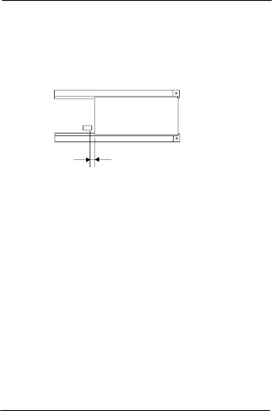
5.24 2nd PCB Confirmation Sensor Positioning
1. Position the 2
ND
Pcb confirmation sensor beam 2mm away from the trailing edge of the
maximum length board.
2. Confirm that carrier does not interfere with the sensor bracket when the conveyor width is
set to minimum.
Max length Pcb
CP-643E (457mm)
2mm
Figure 40

FK-9F98-05 CP-643E Training Text for Service Engineers
Edition 5.0 Chapter 5. Loader and Conveyor Adjustment [27/28]
Fuji Machine Mfg. Co., Ltd. Okazaki
SMT Equipment Quality Assurance Dept.
Technical Support Div. Section No.2
5-
27
5.25 Adjustment of Cylinder Controller
1. Press [F3, Loader] à [F5, Loader Pos.] à [F4. Cylinder Adjust] à Enter the ID code to enter to the
cylinder adjusting command.
2. Enter to [F1, Select] and enter the item number of the cylinder which is going to be adjusted or
calibrated.
3. Enter to [F2, Times], and enter “10”.
4. Pressing [F4, START] will activate the start button. Press “START” to calibrate.
10 results of the Max (ms) and Min (ms) will be displayed after the calibration. Adjust the cylinder
controller so that the results will in the appropriate range shown below.
Press Data Save à Print à Ready to print out the results
Calibration Item No. Time (ms) Apertures
(Ref.)
1.IN_Lif UP/DWN IN Lifter Up/Down time 1500±50 2 rev. from
fully closed.
2.IN_C Clmp Fwd_F Reference clamper open/close time at
IN carrier’s forward end.
3.IN_C Clmp Fwd_R Adjustable clamper open/close time at
IN carrier’s forward end.
4.IN_C Clmp Bwd_F Reference clamper open/close time at
IN carrier’s backward end.
5.IN_C Clmp Bwd_R Adjustable clamper open/close time at
IN carrier’s backward end.
Less than 150 No flow control
valve
6.IN_C Move IN carrier Forward/ backward time 3500±250 Refer to 5-28
7.IN_PCB Load Time to load a PCB from IN lifter
downward end pos. to IN carrier
forward end pos.
7000±500
8.Main Clmp_F Reference clamper open/close time at
MAIN conveyor
Less than 150 No aperture.
9.OUT_Lif UP/DWN OUT lifter UP/DWN time 1500±50 2 rev. from
fully closed.
10.OUT_C Clmp Fwd_F Reference clamper open/close time
at OUT carrier’s forward end.
11.OUT_C Clmp Fwd_R Adjustable clamper open/close time
at OUT carrier’s forward end.
12.OUT_C Clmp Bwd_F Reference clamper open/close time
at OUT carrier’s backward end.
13.OUT_C Clmp Bwd_R Adjustable clamper open/close time
at OUT carrier’s backward end.
Less than 150 No flow control
valve
14.OUT_C Move OUT carrier forward/backward time 3500±250 Refer to 5-28
15.OUT_PCB Load Time to load a PCB from OUT
carrier forward end pos. to OUT
lifter downward end pos.
7000±500
16.Main Clmp_R Clamper open/close time at IN conv.
adjustable side
Less than 150 No flow control
valve.
FK-9F98-05 CP-643E Training Text for Service Engineers
Edition 5.0 Chapter 5. Loader and Conveyor Adjustment [28/28]
Fuji Machine Mfg. Co., Ltd. Okazaki
SMT Equipment Quality Assurance Dept.
Technical Support Div. Section No.2
5-
28
? Adjustment of the “6. IN_C MOVE 14. OUT_C MOVE”?
FWD BWD BWD FWD
IN cont. OUT cont. OUT cont. IN cont.
BWD FWD FWD BWD
IN cont. OUT cont. OUT cont. IN cont.
IN Carrier
OUT Carrier
1. Fully open the OUT controller. Adjust the IN side speed controller so that the calibration
times reaches 3000 +/- 150 (ms).
2. Adjust the OUT controller so that the calibration time reaches 3500 +/- 250 (ms).
3. Press the E-stop while the carrier is moving forward and backward. Move the carrier
again and check if the moving speed is within the specified time limits.
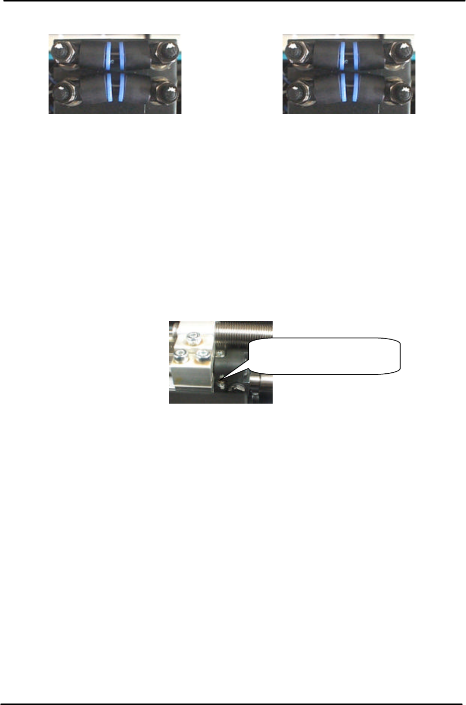
4. To adjust the cushions of the rod-less cylinder, Turn the adjustment screw 3 revolutions
away from the fully closed position.
[Note]:
When using Vacuum Back Up Pins, the loading time is calculated as:
[Loading time measurement value] + 0.72.
(A 360ms software timer is used for timing the vacuum ON/OFF cycle.
Rod-less Cylinder (Cushion)
Adjustment Screw
Figure 42
Figure 41