CP643E.pdf - 第112页
FK-9F98- 05 CP- 643E Training Text for Service Engineers Edition 5.0 Chapter 7. Camera Adjustment [ 7 / 10] Fuji Machine Mfg. Co., Ltd. Okazaki SMT Equipment Quality Assurance Dept. Technical Support Div. Section No.2 7-…
FK-9F98-05 CP-643E Training Text for Service Engineers
Edition 5.0 Chapter 7. Camera Adjustment [6/10]
Fuji Machine Mfg. Co., Ltd. Okazaki
SMT Equipment Quality Assurance Dept.
Technical Support Div. Section No.2
7-6
7.5 Wide / Narrow Camera Skew and Resolution Adjustment
1. The camera skew adjustment is performed in order to align the camera with the X- and the Y- axes.
This is vital for determining accurate angular compensation at station 10 (FQ).
2. The camera resolution indicates the size of a pixel in the X and the Y direction. If the camera
resolution lies outside the specified range, the dimensions of the component inspected will not match
the data contained in the part data, and a vision processing error will occur.
3. Turn the 11
th
station (Y029) and 10
th
station solenoid valves OFF (Y031) with the cam at 0 degrees.
4. Put the wide camera inspection jig on Head A, nozzle No.1.
5. Inch the jig to the 11
th
station and set the cam at 200 degrees.
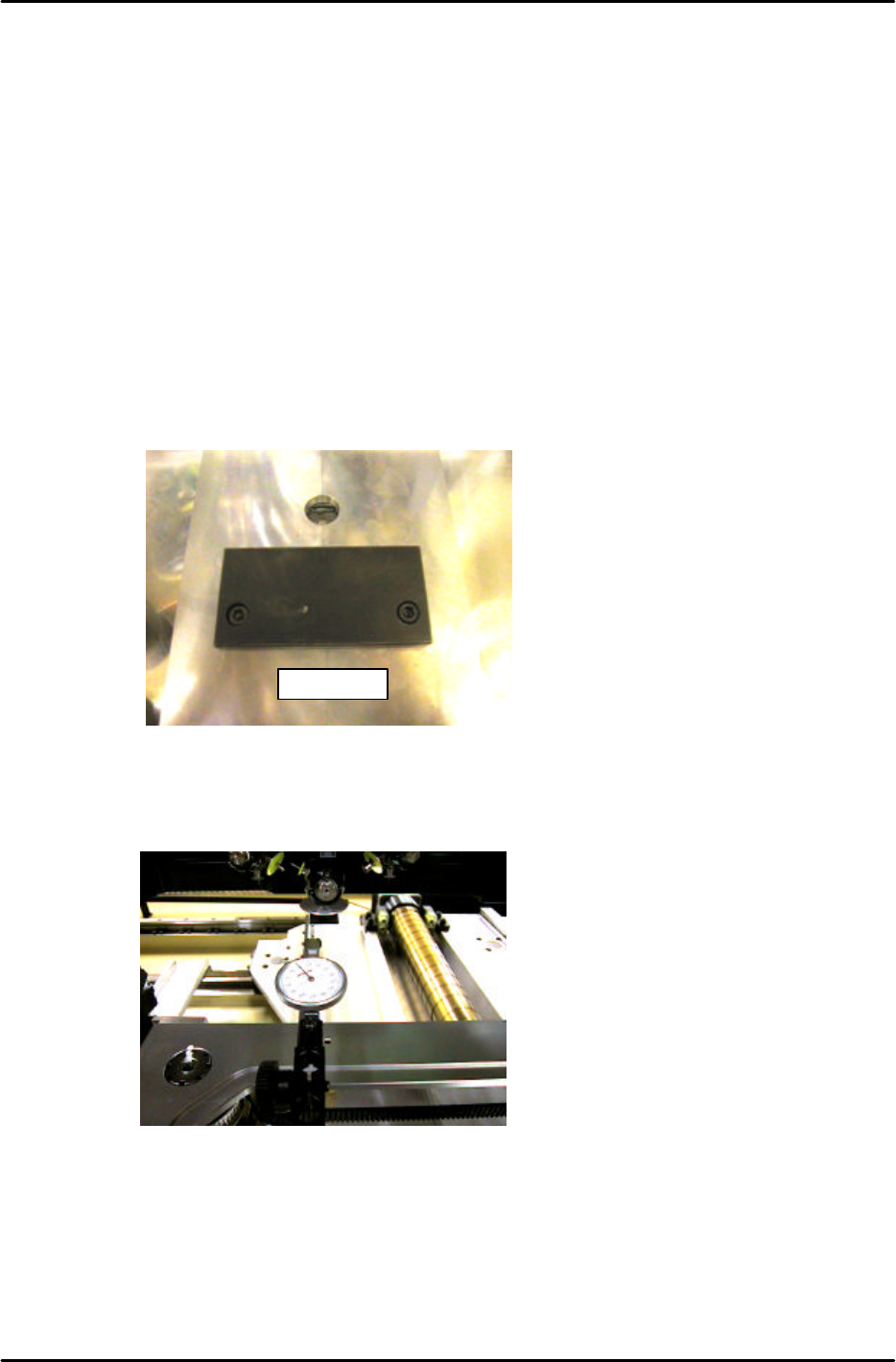
7. Remove the back up plates and attach the “XY Slide (magnet stand)” to the XY table, see Figure 13:
8. Set the dial gauge stand on the magnet stand and set the dial gauge tip to the horizontal flat edge of
the jig, see figure 14:
9. Set the X-axis inching speed to 1% and then inch the dial gauge tip from right to left across the
horizontal flat edge of the jig. Rotate the shaft until the dial gauge shows that the jig is parallel to the
X-axis. (Tol: 0 +/- 0.01mm)
10. Remove the dial gauge and inch the C-axis until the angle is 0 degrees and the jig is half way
between the 11
th
and 12
th
stations.
DCPJ0670
Figure 13
Figure 14
FK-9F98-05 CP-643E Training Text for Service Engineers
Edition 5.0 Chapter 7. Camera Adjustment [7/10]
Fuji Machine Mfg. Co., Ltd. Okazaki
SMT Equipment Quality Assurance Dept.
Technical Support Div. Section No.2
7-7
11. To automatically send the jig to the 6
th
station at 200 degrees use the following commands:
[SET] → [PROPER] → [CAMERA ] → [POSITION 1] → START
12. To perform the measurement procedure press [MEASURE] → START.
13. The camera skew and resolution should be in the tolerances shown below:
Delta Q (skew) 0 +/- 0.05 deg.
Wide camera resolution X & Y 61.19 to 65.13 um/pixel
14. If the resolution is out of range, loosen the lens cover and adjust the camera height. Afterwards,
reset the gap between the lens cover and the prism box to 0.5mm.
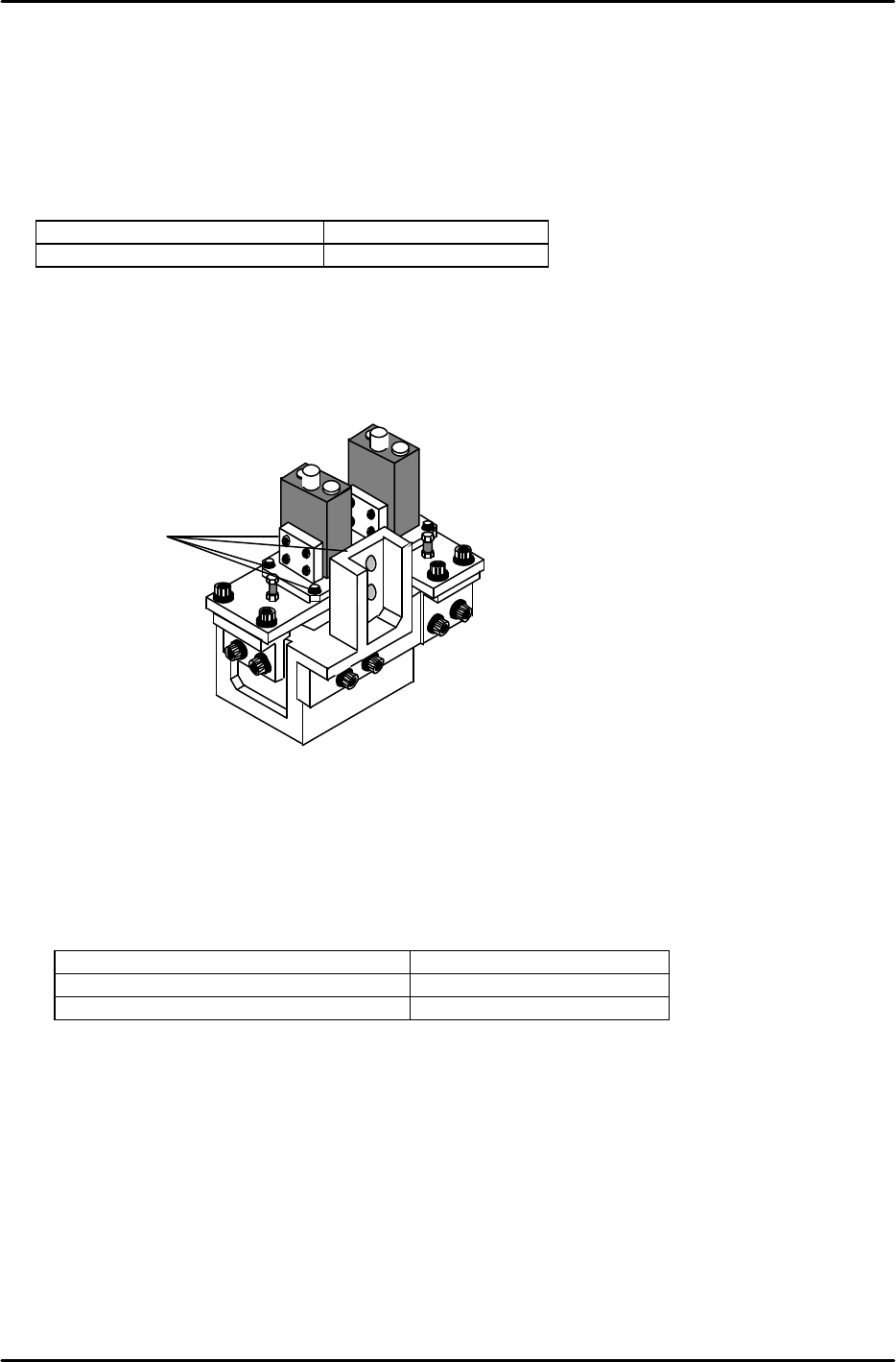
15. To adjust Delta Q loosen the delta Q positioning bolts (1) (see figure 15) and change the camera
angle relative to the prism box.
16. Once the delta Q is set within tolerance: 0 +/- 0.05, lock the delta Q positioning bolts with an 2Nm
torque wrench. After locking the bolts confirm that the delta Q value is still within tolerance.
17. Having finished the wide camera skew and resolution adjustment, repeat the procedure for the
narrow camera. Remember to use the narrow camera inspection jig and set the skew and
resolution values within the tolerances shown below:
Delta Q (skew) 0 +/- 0.05 deg.
Narrow Camera Resolution X & Y 21.09 to 22.44 um/pixel
0603 Narrow Camera Resolution X & Y 11.50 to 12.50 um/pixel
18. Once the calibration procedure has been completed for both cameras, press [POSITION 2] →
START, and the shaft will return to its original position.
19. Remove the inspection jig from the No.1 slot of head A and replace any nozzles that have been
removed.
20. Run a nozzle center check in order to update the calibration data.
Rear View
Figure 15
1

FK-9F98-05 CP-643E Training Text for Service Engineers
Edition 5.0 Chapter 7. Camera Adjustment [8/10]
Fuji Machine Mfg. Co., Ltd. Okazaki
SMT Equipment Quality Assurance Dept.
Technical Support Div. Section No.2
7-8
7.6 Gain Adjustment
1. Insert a clean 0.7mm nozzle in holder A, nozzle 1. Ensure that the reflective seal is properly flattened
down.
2. Inch the nozzle to station 6 at 200 degrees.
3. Press SET à MANUAL à VISION à TRACE à ID code to turn on “RESULT, No.0”.
4. Adjust the gain volume to set both narrow and wide cameras to between 0.65 and 0.7mm, 650 and
700. (Target value = 675.) This value can be seen on the monitor while running the center test.
5. When the 0603 camera has been installed;
The measurement value should be 0.37mm to 0.4mm [Display : 370 to 400 (Target value = 385)]
IMPORTANT:
The resolution values will change if the camera gain is changed. So it is necessary to check the
camera resolution again if the gain has been changed. If the resolution is out of tolerance, adjust the
camera positioning again.