CP643E.pdf - 第47页
FK-9F98-05 CP- 643E Training Text for Service Engineers Edition 5.0 Chapter 4. Station Adjustment [ 2 /18] Fuji Machine Mfg. Co., Ltd. Okazaki SMT Equipment Quality Assurance Dept. Technical Support Div. Section No.2 4- …
FK-9F98-05 CP-643E Training Text for Service Engineers
Edition 5.0 Chapter 4. Station Adjustment [1/18]
Fuji Machine Mfg. Co., Ltd. Okazaki
SMT Equipment Quality Assurance Dept.
Technical Support Div. Section No.2
4-
1
Chapter 4 Station Adjustment
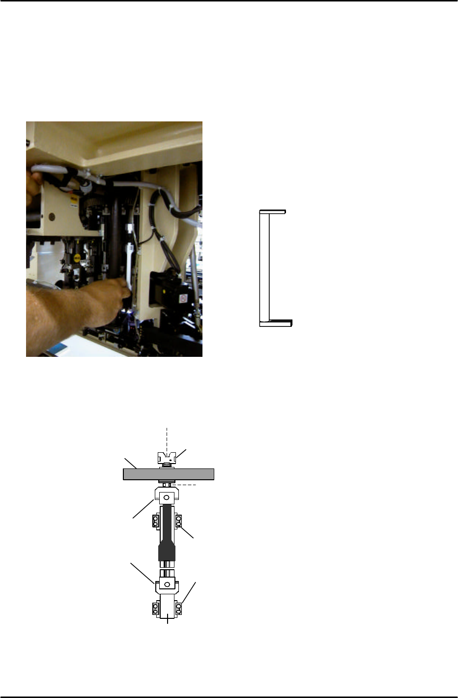
4.1 Shaft Assembly Adjustment
1. Rotate shaft A to the 19
th
station.
2. Make sure that there is a nozzle holder on shaft A.
3. Check the alignment of the holder and clutch. Use the jig indicated in Fig.1.
4. If the holder and clutch are not aligned correctly, use a 10mm spanner at position A in fig. 2; and
a 3.0mm L-wrench at position B, to loosen the shaft assembly and realign them.
5. When the clutch and holder on the shaft assembly are correctly aligned, there should be no
resistance with the jig.
6. Finally, in preparation for the adjustments that follow, remove the holder from shaft A.
Coupling
Nut retainer
A
Helical gear
Clutch
Linear guide rail
B
Figure 2
19
TH
station alignment Jig No. WPJ0102
Figure 1
FK-9F98-05 CP-643E Training Text for Service Engineers
Edition 5.0 Chapter 4. Station Adjustment [2/18]
Fuji Machine Mfg. Co., Ltd. Okazaki
SMT Equipment Quality Assurance Dept.
Technical Support Div. Section No.2
4-
2
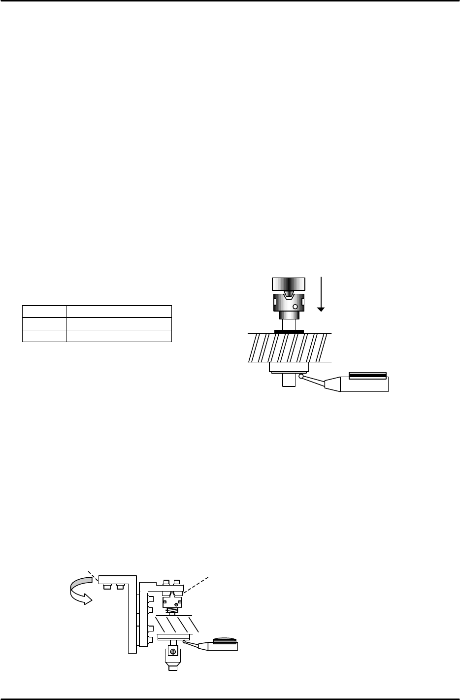
4.2 Stroke Adjustment
Adjust the clutch stroke of stations; 3,10,12 and 13 as described below.
1. Remove the sensor bracket at station 12 and put it aside.
2. Measure and record the deflection of each shaft clutch at 200 degrees. (rotate the shaft to find
the absolute low point.) When the clutch is at the downward end position and manually rotated,
the dial indicator should read within 0.01 to 0.02mm.
3. After measuring all the shafts, find the shaft with the least deflection amount and record it as the
“LOW” shaft.
4. Using the LOW shaft, set the stroke at stations 3,10,12, and 13.
Turn the solenoid valve ON only for the station being adjusted at the time. Otherwise, all valves
should be OFF. ( No valve used at the 12
th
station)
5. When the rotor engages with the nozzle clutch at 200 degrees, adjust the rod so that the nozzle
clutch is pressed downward on the LOW shaft 0.30 to 0.35mm. (0.31 is the ideal value)
<I/O à Standard I/O à OUT>
Y030 FQ SOL
Y022 PQ ROT SOL ON
Y02C PRQ ROT SOL ON
4.3 Station 5 Origin Position and Stroke Adjustment
1. This adjustment should be performed with the servo power OFF.
2. Move the LOW shaft to station 5 and set at 200 degrees.
3. Engage and align the 5th station clutch (1) with the reference shaft, by adjusting the position of
bracket (2):
1
2
Figure 4
Scale --- 0.3mm
Figure 3
FK-9F98-05 CP-643E Training Text for Service Engineers
Edition 5.0 Chapter 4. Station Adjustment [3/18]
Fuji Machine Mfg. Co., Ltd. Okazaki
SMT Equipment Quality Assurance Dept.
Technical Support Div. Section No.2
4-
3
4. To check that the clutch and low shaft are properly aligned, measure the difference in stroke when
the shaft is at 0, 90, 180, and 270 degrees. Tolerance is 0.030mm. Adjust bracket (2) if necessary.
5. Once the clutch is aligned within tolerance, proceed to set the 5
th
station stroke.
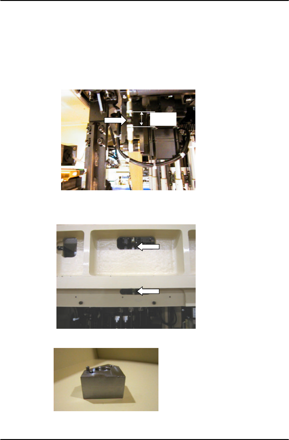
6. Set the length of the stroke-adjusting rod, (located under the cam box at the front of the machine),
to 21mm. (See figure 5 below) When setting the stroke, ensure that the adjustment nut (at the tip
of the arrow), is in the center of the stroke-adjusting rod.
7. With the cam at 200 degrees, set the 5
th
station stroke within a range of 0.30 to 0.35mm, (0.31mm
is the ideal value). Set the stroke by turning the stroke-adjusting rod, (located at the front of the
machine in front of the FQ motor). (See figure 6 below)
8. Once the stroke adjustment is completed, place the 5
th
station origin jig, on shaft A:
Station 5 origin jig Jig No. 71615WPJ0650
Figure 7
Figure 5
21mm
Figure 6