CP643E.pdf - 第11页
FK-9F98-05 CP- 643E Training Text for Service Engineers Edition 5.0 C ontents - List of Current Pages Fuji Machine Mfg. Co., Ltd. Okazaki SMT Equipment Quality Assurance Dept. Technical Support Div. Section No.2 VIII Not…

FK-9F98-05 CP-643E Training Text for Service Engineers
Edition 5.0 Contents- List of Current Pages
Fuji Machine Mfg. Co., Ltd. Okazaki
SMT Equipment Quality Assurance Dept.
Technical Support Div. Section No.2
VII
Chapter 6 Servo System Adjustment………….…………...(Edition 5.0)
(section No.) (Page No.)
6.1 Servo Pack Parameter Check 6-1
6.2 Servo Pack Zero Adjustment Preparation 6-1
6.3 D-axis Servo Pack Zero Adjustment 6-2
6.4 C and X Axis Servo Pack Zero Adjustment 6-2
6.5 FQ, FRQ, NC, Y, and Z axis Servo Pack Zero Adjustment 6-2
6.6 D-axis Gain and Motion Check 6-3
6.7 C and X axes Gain and Motion Check 6-4
6.8 Y, Z, FQ, FRQ, and NC axes Gain / Motion Check 6-4
Chapter 7 Camera Adjustment……………….……….…….(Edition 5.0)
(section No.) (Page No.)
7.1 Parts Camera Removal 7-1
7.2 Camera Settings 7-2
7.3 Camera Centering 7-3
7.4 Focus Adjustments 7-5
7.5 Wide / Narrow Camera Resolution (Station 5) and Delta Q Calibration 7-6
7.6 Gain Adjustment 7-8
7.7 Mark Camera Focus Adjustment 7-9
7.7.1 Focus Adjustment 7-9
7.7.2 Mark camera Resolution, Delta Q and XC YC Calibration 7-10
Chapter 8 Placing Accuracy Measurement…………….….(Edition 5.0)
(section No.) (Page No.)
8.1 PAM Calibration 8-1
8.2 Placing Accuracy Check by Fuji96 Board 8-6
Chapter 9 Miscellaneous Adjustments………………...…..(Edition 5.0)
(section No.) (Page No.)
9.1 Backup pin Adjustment 9-1
Supplemental Information
1. CP-643 Servo Amplifier Parameter Sheet
2. Servo Pack Error Code Listing

FK-9F98-05 CP-643E Training Text for Service Engineers
Edition 5.0 Contents- List of Current Pages
Fuji Machine Mfg. Co., Ltd. Okazaki
SMT Equipment Quality Assurance Dept.
Technical Support Div. Section No.2
VIII
Notes:
FK-9F98-05 CP-643E Training Text for Service Engineers
Edition 5.0 Chapter 1. Initial Set-up [1/2]
Fuji Machine Mfg. Co., Ltd. Okazaki
SMT Equipment Quality Assurance Dept.
Technical Support Div. Section No.2
1-1
Chapter 1 Initial Set-up
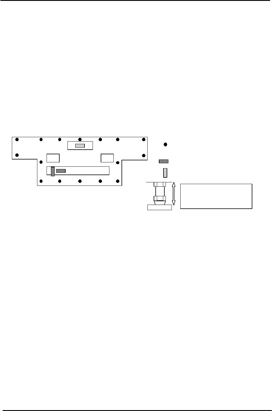
1.1 Machine Leveling
Equipment: 0.02mm/1m track level
1. Level the machine by placing leveling blocks at the positions illustrated below.
2. Use bolts A, B, E, and F, for initial leveling.
3. Confirm leveling in the X and Y directions once all the bolts have been securely
tightened.
4. Once the initial leveling is completed, lock the remaining bolts shown in the
diagram below.
1.2 Machine Utilities
Refer to the CP-6 series Mechanical Reference Manual for information regarding the utility
connections needed for this machine.
• Power
• Air
For stability reasons, it is
better to keep the leveling
bolts as short as possible.
Leveling positions.
= Spirit Level (tolerance 0.04/1000mm)
= Spirit Level (tolerance 0.08/1000mm)
A B
I
H
G
C
D
E
CP-643E
J
K
L M
N
P
O
F
Figure 1