CP643E.pdf - 第67页
FK-9F98-05 CP- 643E Training Text for Service Engineers Edition 5.0 Chapter 5. Loader and Conveyor Adjustment [ 4 / 28 ] Fuji Machine Mfg. Co., Ltd. Okazaki SMT Equipment Quality Assurance Dept. Technical Support Div. Se…
FK-9F98-05 CP-643E Training Text for Service Engineers
Edition 5.0 Chapter 5. Loader and Conveyor Adjustment [3/28]
Fuji Machine Mfg. Co., Ltd. Okazaki
SMT Equipment Quality Assurance Dept.
Technical Support Div. Section No.2
5-
3
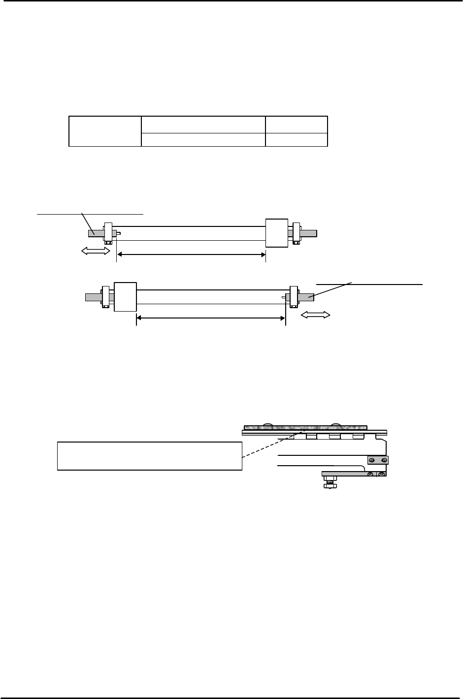
5.4 Rod-less Cylinder Stroke Check
1. Check the stroke of the IN and OUT carrier rod-less cylinders as indicated in the following
table and Fig. 6.
2. Set the stroke by adjusting the backward end shock absorber on the rod-less cylinder.
CP-643E IN carrier (Upper side) 629.0 mm
OUT carrier (Lower side) 613.5 mm
Note: Check the stroke after locking the IN & OUT carrier at their forward ends.
5.5 Conveyor Assembly Accuracy Check
1. Confirm that the PCB guide plates (2.5mm) are aligned with the upper surface of the
conveyors.
2. Confirm that the conveyor width change unit and stopper unit move smoothly by
hand.
3. Check whether the lifter plate is bent or scratched.
4. Check the maximum, minimum width and the entrance/exit of the IN & OUT conveyor.
5. The difference between the IN and OUT conveyors must be within 0.2mm. Change the
connecting chain if the value is out of tolerance.
IN Carrier Rod-less Cylinder
Out Carrier Rod-less Cylinder
In Carrier
Backward end shock absorber
Out Carrier
Backward end shock absorber
Figure 6
The Pcb guide plate and the inside surface
of the In/Out conveyor should be aligned.
Figure 7
FK-9F98-05 CP-643E Training Text for Service Engineers
Edition 5.0 Chapter 5. Loader and Conveyor Adjustment [4/28]
Fuji Machine Mfg. Co., Ltd. Okazaki
SMT Equipment Quality Assurance Dept.
Technical Support Div. Section No.2
5-
4
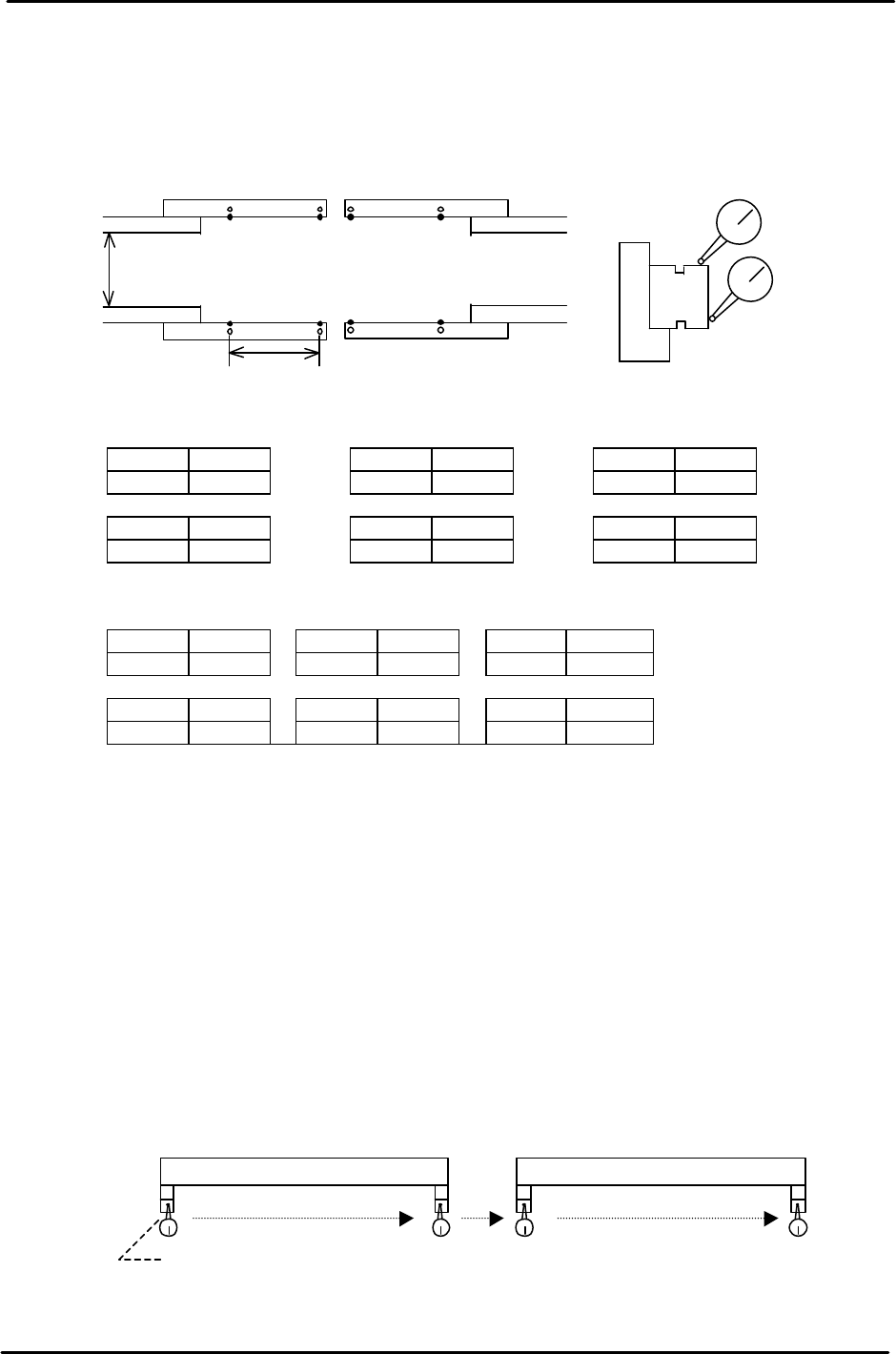
5.6 Carrier Accuracy Check
1. Set a dial indicator on the XY Table. Check the parallelism and height of the reference and
adjustable side LM guides at the positions indicated in Fig. 8.
<Parallelism> should be less than +/-0.10mm (from the zero reference position)
A B A’ B’ A A’
0 0 0
C D C’ D’ C C’
0 0 0
<Height> should be less than +/-0.20mm (from the zero reference position)
A-A’, C-C’ should be less than 0.15mm)
A B A’ B’ A A’
0 0 0
C D C’ D’ C C’
0 0 0
5.7 Joint Plate Alignment
Joint plates mounted on the In/Out carriers, engage with the main table moveable rail when Z is
lifted to the Z Load position. (Keeping the carriers and main table moveable rail aligned)
1. Check the position of the IN & OUT carrier width adjustment joint. The standard joint spacer is
0.5mm. The spacer thickness can be changed in order to align the 4 joint plates.
Spacer thickness must be within 0.5mm +/-0.2mm. (0.3mm to 0.7mm)
2. Move the carrier to the forward end and set a dial gauge on the main table. Move the X-axis
to check the parallelism of each joint.
3. Target parallelism of the 4 joints must be within 0.1mm.
B
A’
D
B’
C’C
D’
A
400mm
<Parallelism>
<Height>
200mm
Figure 8
In Carrier Out Carrier
0 reference position
Figure 9
FK-9F98-05 CP-643E Training Text for Service Engineers
Edition 5.0 Chapter 5. Loader and Conveyor Adjustment [5/28]
Fuji Machine Mfg. Co., Ltd. Okazaki
SMT Equipment Quality Assurance Dept.
Technical Support Div. Section No.2
5-
5
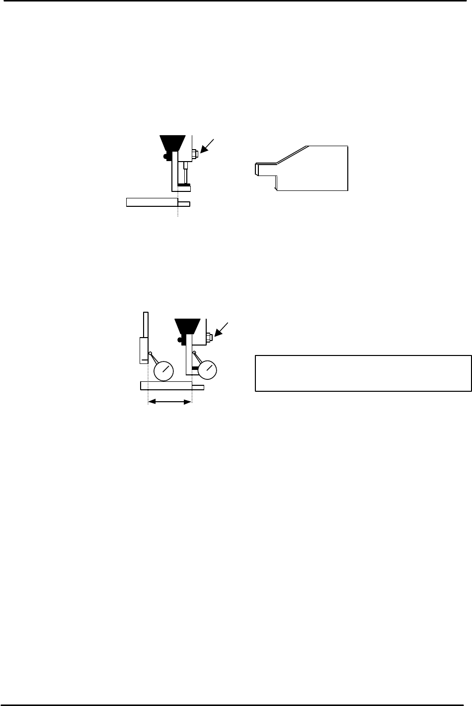
5.8 Carrier Claw Position Adjustment
1. Fix both the IN and OUT carriers at the forward end. Check if there is any play in the X-direction.
2. Check the claw tilt and pitch. There must about 0.2mm clearance between the retaining pin and
claw.
3. Close the claw on the reference side. Using a jig, adjust the set-screws so the conveyor rail
aligns with the inner face of the carrier claw. After adjustment, tighten all screw nuts.
4. For the secondary rail carrier claw adjustment: Set a dial gauge on the joint plate. Write down the
Y pulse count at this position. Then, move to the inside surface of the carrier claw. Calculate the
total pulse count between these two positions. Adjust the bolt accordingly to set the distance
between the joint plate and claw to 2200 pulses. Then, lock the 4 set-screw nuts.
For CP-643
(Jig No.:Z5413WPJ0132)
View looking in from the
exit conveyor
Adj. Screw
Figure 10
Adj. Screw
2200 Pulses
NOTE:
Set to 2190 Pulses for the out carrier.
Figure 11