CP643E.pdf - 第32页
FK-9F98-05 CP-643E Training Text for Service Engineers Edition 5.0 Chapter 3. X, Y, Z and D-axes Adjustment [ 13 /26] Fuji Machine Mfg. Co., Ltd. Okazaki SMT Equipment Quality Assurance Dept. Technical Support Div. Secti…
FK-9F98-05 CP-643E Training Text for Service Engineers
Edition 5.0 Chapter 3. X, Y, Z and D-axes Adjustment [12/26]
Fuji Machine Mfg. Co., Ltd. Okazaki
SMT Equipment Quality Assurance Dept.
Technical Support Div. Section No.2
3-12
3.9 Z -axis Zero Setting (0.002mm/Pulse)
Note: The table must be level before making Z-axis adjustments.
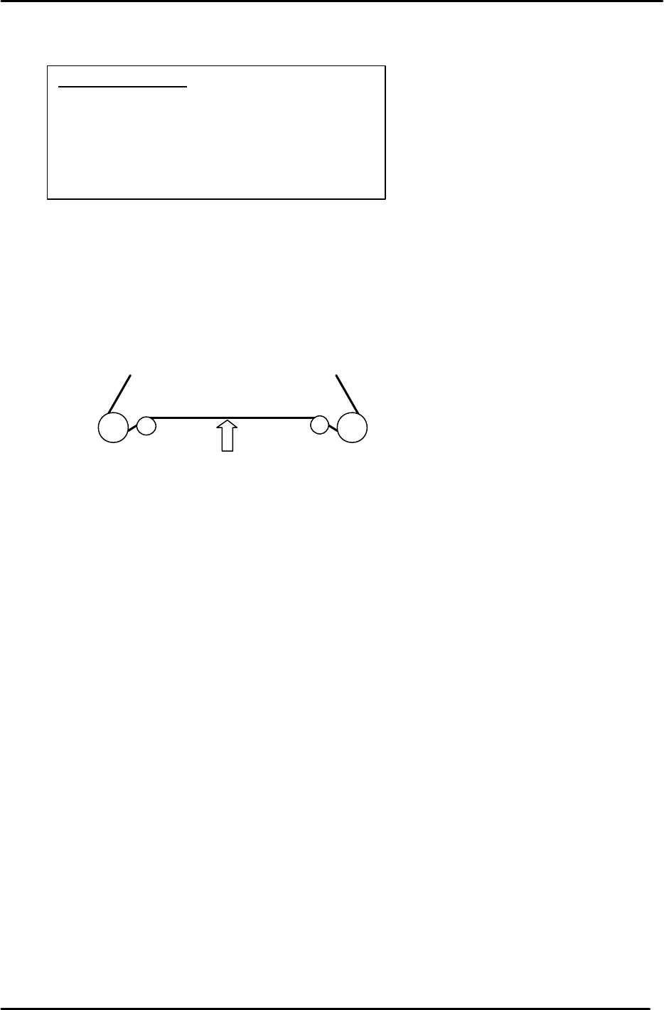
1. Set the tension of the Z-axis timing belt as follows:
CP-643E = 100 +/- 2 Hz.
Measure the belt at a position where the span is the longest (front or back)
2. Remove the minus OT flag for the Z-axis.
3. Loosen the mechanical lock at the Z-axis drive pulley. (make sure the motor shaft turns freely)
4. In Mecha-check mode, complete zero setting by blocking the zero set sensor with a scale.
5. Inch the Z servo count to – 900 pulses.
6. Lower the Z-axis toward the (–) mechanical stopper and insert a 0.2mm feeler gauge between
the stopper and base of the table.
8. Lock the four securing bolts for the mechanical lock with a 1N.m torque wrench.
9. Check that the pulse count is close to – 900 with a 0.2 gauge between the minus stopper and
table.
10. Attach the – OT flag with the pulse count at – 500 pulses.
11. To set the software travel limit, find the pulse count where the minus OT sensor just turns ON.
Set the Z Min limit position at the host PC.
Note: Set the Maximum limit after the loader adjustment has been completed.
(Refer to the tables in step 13 for details)
Equipment Checklist
1- 3mm L-wrench
1- 4mm T-wrench
1- Tension Meter
1- 1Nm torque wrench with 2mm attachment
1- 0.2 mm feeler gauge
1- 2.5mm T-wrench
Measuring point
Figure 18
FK-9F98-05 CP-643E Training Text for Service Engineers
Edition 5.0 Chapter 3. X, Y, Z and D-axes Adjustment [13/26]
Fuji Machine Mfg. Co., Ltd. Okazaki
SMT Equipment Quality Assurance Dept.
Technical Support Div. Section No.2
3-13
12. Lift the Z-axis to the + mechanical stopper and ensure the pulse count is within the following
range.
(CP-643E) 23650±250
13. Check the sensor reaction in I/O.
<I/O à ETC à Servo 1 à IN>
SX00C Z AXIS + OT
SX00D Z AXIS – OT
SX00E Z AXIS ZERO
14. The following table lists the Z axis proper and physical data reference values.
Z-axis Servo Count Values
Z-axis Servo counter table 0.002mm/Pulse Standard Value (Reference value)
Plus Mechanical Stopper 23650±250
Max Limit Pos. Z Same as plus OT sensor value
Plus OT Sensor <SX00C> {ZL (Upper) +500}+/-50
Loading Pos. ZL IN 22400 to 22900
Loading Pos. ZL OUT 22400 to 22900
Middle Loading Pos. ML ZL (Lower) – 10500
Upward End Sensor 1 ON ML –125±50
Upward End Sensor 2 ON Z0 + 2300±50
Downward End Sensor OFF Z0 + 400±50
Middle OT Sensor ON Z0 + 150±50
Z0 5500±300
Zero Set Sensor ON <SX00E> 1000±50
Minus OT Sensor ON <SX00D> – 500±50
Min Limit Pos. Z Same as minus OT sensor value
Minus Mechanical Stopper – 1000±50
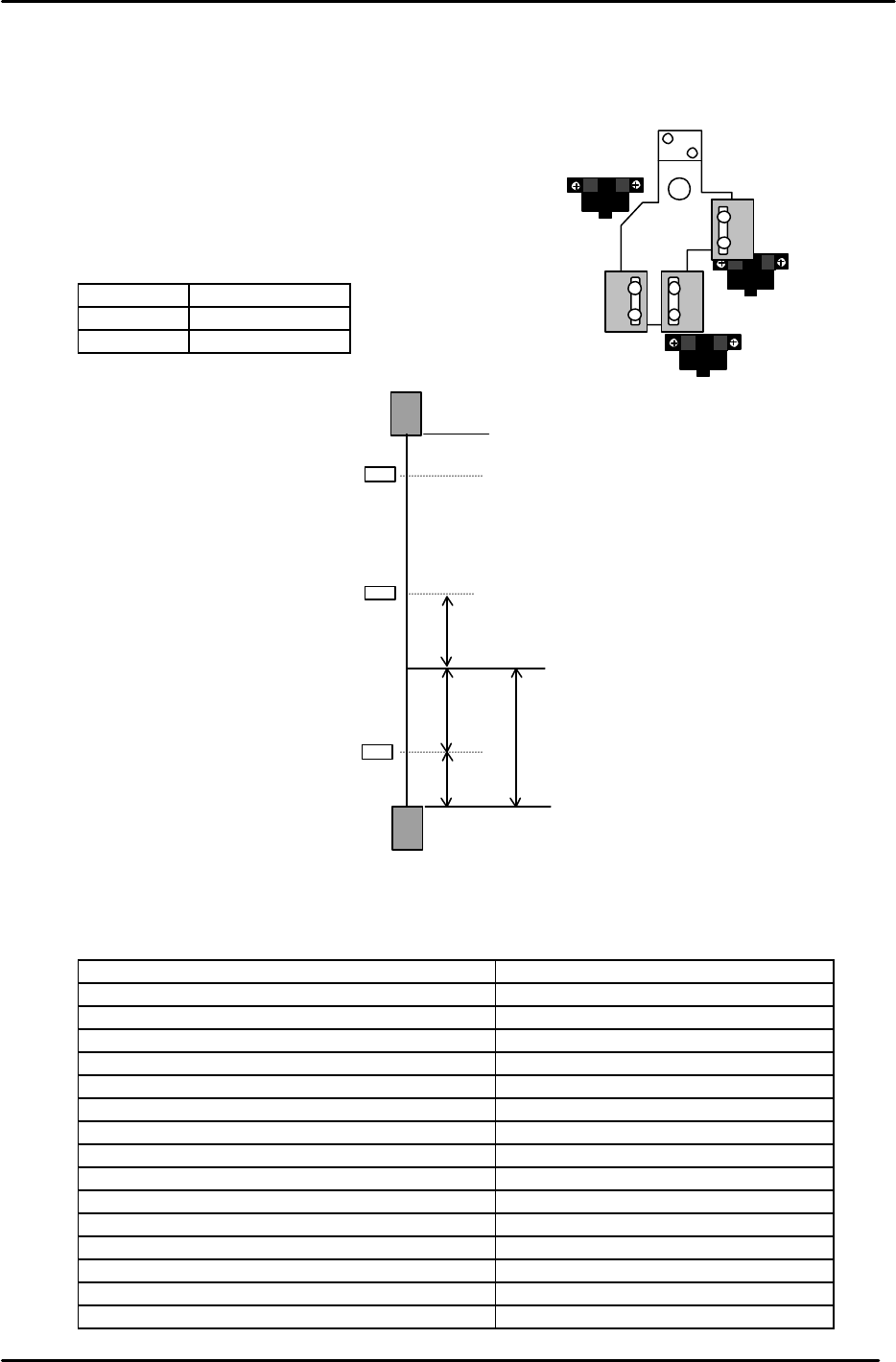
Zero set sensor
+OT sensor
- OT sensor
Figure 19
– OT
+ OT
+ Stopper
– Stopper
Zero Set Sensor
(Min Limit Position)
(Max Limit Position)
500
0 Position
1000
1000
500
Z axis
Figure 19
{ZL (Upper)
+
500 pulses} +/- 50 pulses
Note: ZL upper is calculated in chapter 5.
Set the maximum limit after determining
the ZL upper position.
FK-9F98-05 CP-643E Training Text for Service Engineers
Edition 5.0 Chapter 3. X, Y, Z and D-axes Adjustment [14/26]
Fuji Machine Mfg. Co., Ltd. Okazaki
SMT Equipment Quality Assurance Dept.
Technical Support Div. Section No.2
3-14
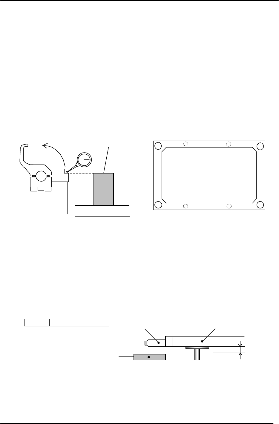
3.10 Back-up Plate Height and Flatness Adjustment
1. After zero-setting the Z-axis, raise the table to 5000 pulses. Place the height
adjustment jig on the backup plate.
2. Adjust the 4 bolts so the top surface of the jig and clamper base are equal.
3. Note: When changing the Z-axis position, the spring force to the plate changes
and the jig’s height will slightly differ. Please pay attention when adjusting.
(Adjust it within range so that the Z-axis and backup plate are synchronized.)
4. Flatness tolerance ----- less than 0.1mm
(There are 4 adjustment bolts. It is better to set one height as reference and measure with a
dial gauge.)
3.11 Back-up Pin Interference Prevention Sensor Adjustment
1. Adjust the 4 flags so the sensors will turn ON, when the clearance between the Y-table and the
backup plate is 2mm. (Set the flags so the 4 sensors activate within 50 pulses of each other.)
2. Check the sensor reaction in I/O.
<I/O ? Standard I/O? IN>
X031 Back up Pin Check
Back up plate
Jig
Z5313WPJ0130
Figure 20
Figure 21
Adjustment bolts
Adjustment bolts
Backup Plate
Flag
Proximity SW
2mm
Figure 22