CP643E.pdf - 第19页
FK-9F98-05 CP-643E Training Text for Service Engineers Edition 5.0 Chapter 2. Cam Box Adjustment [ 6 /6] Fuji Machine Mfg. Co., Ltd. Okazaki SMT Equipment Quality Assurance Dept. Technical Support Div. Section No.2 2- 6 …
FK-9F98-05 CP-643E Training Text for Service Engineers
Edition 5.0 Chapter 2. Cam Box Adjustment [5/6]
Fuji Machine Mfg. Co., Ltd. Okazaki
SMT Equipment Quality Assurance Dept.
Technical Support Div. Section No.2
2-5
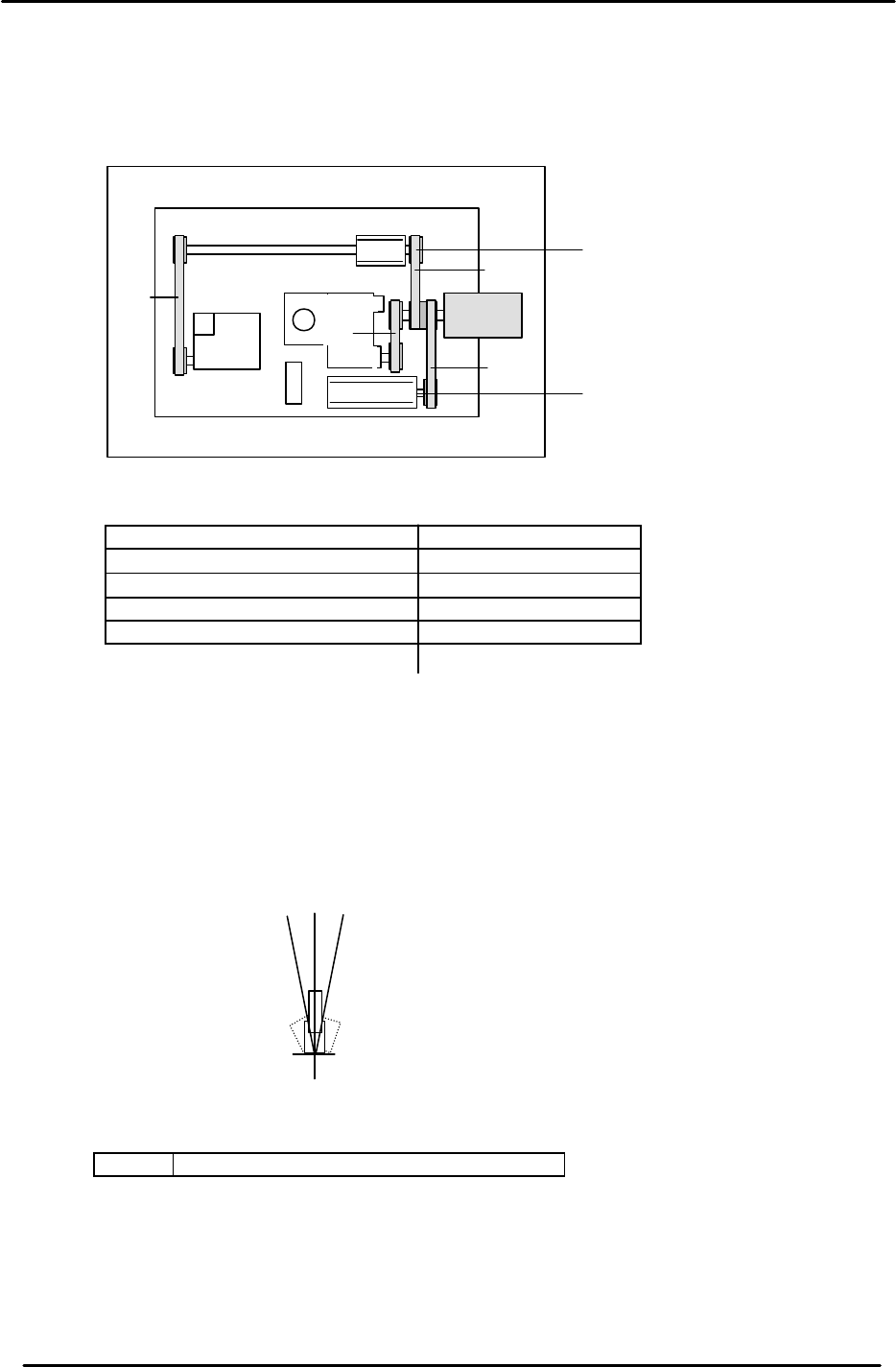
2.9 Cam-axis Timing Belt Tension Adjustment
Timing Belt Tensions in Cam box
Axis Appropriate value (Hz)
¬ = Cam Axis A to Cam Motor 112.0 ± 5
- = Cam Axis B to Cam Motor 83.5 ± 5
® = Nozzle Index to Cam Motor 198.0 ± 5
¯ = Cam Axis B to Theta Index 72.0 ± 5
2.10 Cam Axis Origin Flag Adjustment
1. Set the cam angle to zero.
2. The center of the dog must align with the center of the sensor at cam 0. (0±1 degree)
Note: If the flag is centered, the sensor should turn OFF at 5 degrees on either side of 0.
<I/O à Servo I/O 1 à IN>
SX006 CAM ZERO POS (Cam Origin Position)
3. Confirm that the debugging dog next to the zero set sensor is tightened.
“A “ Cam
“B“ Cam
¬
-
®
¯
Figure 8
0
- 5
+ 5

FK-9F98-05 CP-643E Training Text for Service Engineers
Edition 5.0 Chapter 2. Cam Box Adjustment [6/6]
Fuji Machine Mfg. Co., Ltd. Okazaki
SMT Equipment Quality Assurance Dept.
Technical Support Div. Section No.2
2-6
Notes:

FK-9F98-05 CP-643E Training Text for Service Engineers
Edition 5.0 Chapter 3. X, Y, Z and D-axes Adjustment [1/26]
Fuji Machine Mfg. Co., Ltd. Okazaki
SMT Equipment Quality Assurance Dept.
Technical Support Div. Section No.2
3-1
CHAPTER 3 X, Y, Z and D-axis Adjustment
3.1 Interference Check
1. Confirm that the X and Y couplings are loosened and check for any interference by moving the
axes through their full movement range manually.
2. Check that the sensors and sensor flags do not collide.
3.2 X-axis Zero Setting (0.01mm/pulse)
1. Boot up the Mechanical check software, select the INCH command and move the cursor to the
X-axis by using the + page and – page keys.
2. Select SERVO ON and press the Start button. The motor will begin turning.
3. Interrupt the X-axis zero set sensor using a scale to complete zero setting.
4. When zero setting is completed, move the minus over travel flag to the left end, press axis
change key 1 and drive the counter value to 200 pulses via the inching keys. Then, tighten the
motor side coupling bolt to 12Nm.
5. Set the X-axis to –300 pulses via the inching keys, move the table until it is in contact with the
plus mechanical stopper. Then, tighten the coupling on the ball-screw side. (12Nm)
6. Press the emergency stop button. Record the counter value when the X-axis is manually pushed
against the plus mechanical stopper.
7. Adjust the OT flag to turn the minus over travel sensor ON when bringing the table back 50
pulses from the plus mechanical stopper. Record the counter value.
8. Set the counter to plus 1000 pulses. Adjust the flag to turn the zero set sensor ON at this
position. Record the counter value.
9. Record the counter value when the table is in contact with the minus mechanical stopper.
10. Adjust the flag to turn the plus over travel sensor ON when bringing the flag 250 pulses back
from the minus mechanical stopper. Record the counter value.
11. For sensor reaction, check I/O.
<I/O à ETC à Servo 2 à IN>
SX004 X AXIS +OT (X Plus Over Travel)
SX005 X AXIS –OT ( X Minus Over Travel)
SX006 X AXIS ZERO (X Zero Set Sensor)
NOTE : Pay attention to “+” and “–” signs. The X-axis counter values appear opposite in value
between mecha-check mode and normal operation mode.
12. Set the software travel limits as follows:
Move the X-axis back 100 pulses from where the – OT sensor turns ON and set the proper
value. (Set the Max Limit Position at the host PC)