CP643E.pdf - 第63页
FK-9F98-05 CP- 643E Training Text for Service Engineers Edition 5.0 Chapter 4. Station Adjustment [ 18 /18] Fuji Machine Mfg. Co., Ltd. Okazaki SMT Equipment Quality Assurance Dept. Technical Support Div. Section No.2 4-…
FK-9F98-05 CP-643E Training Text for Service Engineers
Edition 5.0 Chapter 4. Station Adjustment [17/18]
Fuji Machine Mfg. Co., Ltd. Okazaki
SMT Equipment Quality Assurance Dept.
Technical Support Div. Section No.2
4-
17
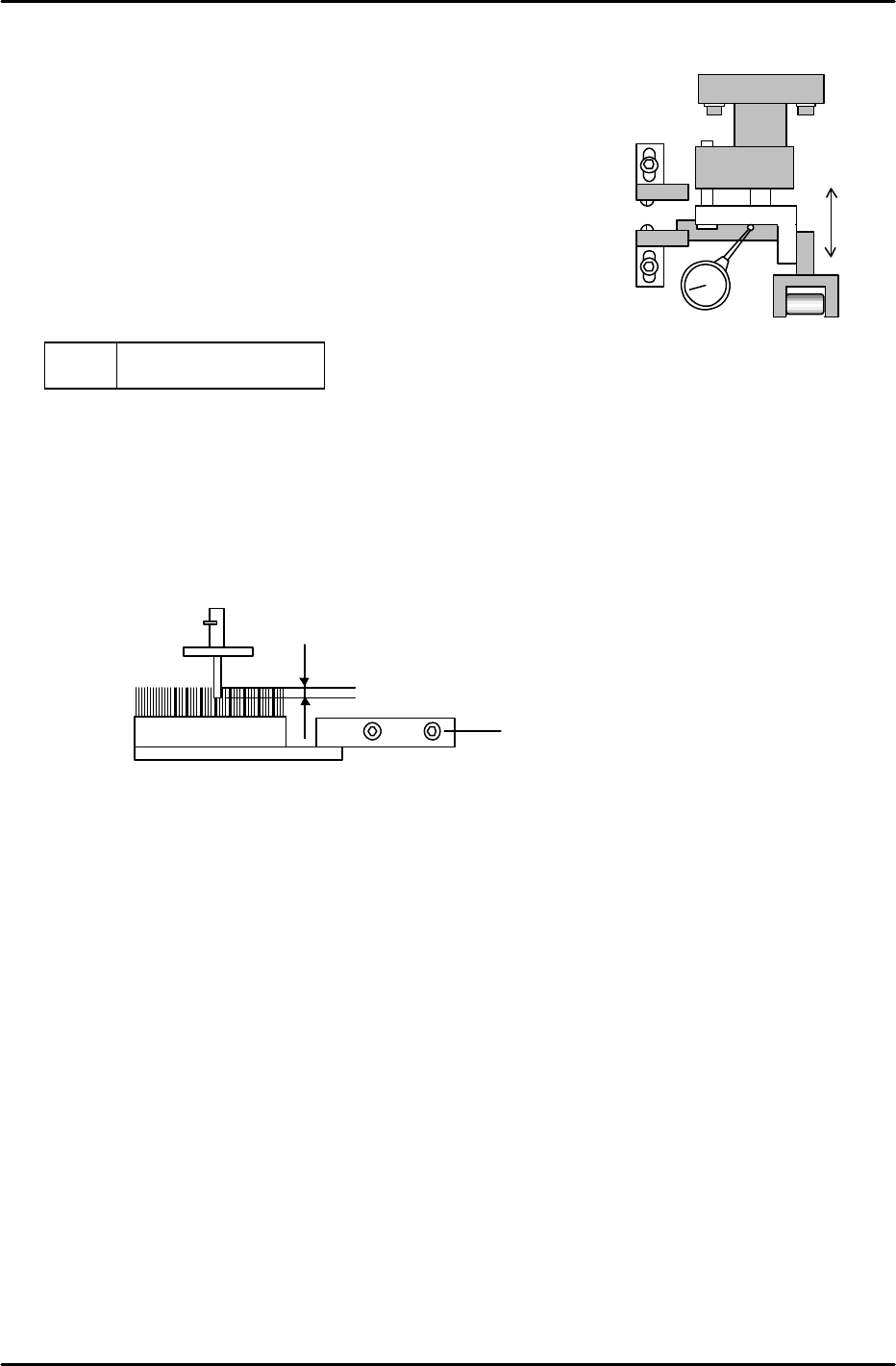
4.21 Forward/Backward End Sensor Adjustment
Adjust the forward and backward end sensors as follows:
1. Using a dial gauge, adjust the backward end sensor so that it
turns OFF when the flag descends 0.3mm from the upward
end position.
2. Adjust the forward end sensor so that it turns OFF when
the flag ascends 0.6mm from the downward end position.
3. Confirm sensor reaction by I/O.
<I/O à Standard I/O à IN>
X03C
X03D
FEEDING FW POS
FEEDING BW POS
4.22 Brush Height Adjustment for Parts Rejection (Station 16)
1. Set a 1.3mm nozzle in the holder and move it to station 16. Adjust the brush height so the nozzle
enters the brush 0.5 to 1mm below the top surface of the brush.
4.23 Nozzle Holder Installation
1. Install the filter into the shaft.
2. Apply grease and check the motion of all shafts, then install the holders.
3. Verify the holder and clutch positioning using the alignment jig.
Figure 37
XO3C
XO3D
Installation bolts
Figure 38
0.5 to 1mm into the brush

FK-9F98-05 CP-643E Training Text for Service Engineers
Edition 5.0 Chapter 4. Station Adjustment [18/18]
Fuji Machine Mfg. Co., Ltd. Okazaki
SMT Equipment Quality Assurance Dept.
Technical Support Div. Section No.2
4-
18
Notes:
FK-9F98-05 CP-643E Training Text for Service Engineers
Edition 5.0 Chapter 5. Loader and Conveyor Adjustment [1/28]
Fuji Machine Mfg. Co., Ltd. Okazaki
SMT Equipment Quality Assurance Dept.
Technical Support Div. Section No.2
5-
1
Chapter 5 Loader and Conveyor Adjustment
5.1 Air Leakage Check
1. Check the cylinder tubing and operation by activating the loader solenoid valves manually.
2. Ensure all air tubing is tight and free of air leaks.
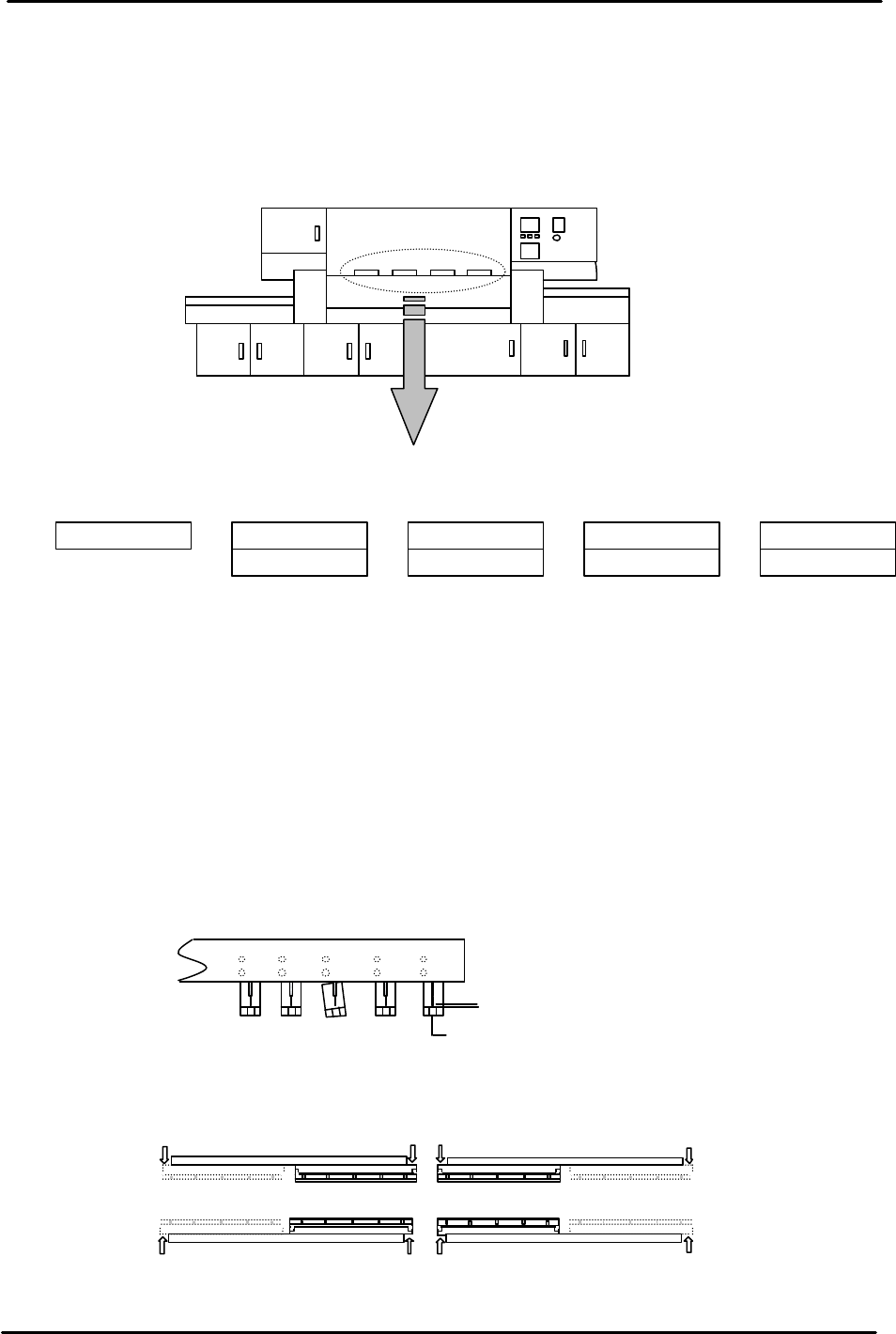
5.2 Carrier Claw and Pin Check
1. Ensure all carrier claws are straight and aligned.
2. Ensure the pin is centered above the cutout in the claw.
3. The pin should be positioned approximately 0.2mm above the claw cutout.
4. Ensure the pins move smoothly in and out.
5. If it is necessary to remove the carrier assembly, remove only the two screws at each
arrow location.
NG
Approx. 0.2mm
C
L
Figure 2
In Carrier
Out Carrier
Figure 3
A
A
A
A
A
A
A A
A
B
B
B
B
B
B B B B
Up
Down
Up
Down
Up Down
Up Down
FWD
BWD
Open
Close
FWD BWD
Moveable Stopper
IN Lifter
Out Carrier claw
Out Pcb Stopper
IN
Pcb Stopper
Out Lifter
In Carrier
In Carrier claw
Out Carrier
CP-643E Loader System Solenoid Valve Arrangement
Up
Down
Open
Close
Figure 1