CP643E.pdf - 第39页
FK-9F98-05 CP-643E Training Text for Service Engineers Edition 5.0 Chapter 3. X, Y, Z and D-axes Adjustment [ 20 /26] Fuji Machine Mfg. Co., Ltd. Okazaki SMT Equipment Quality Assurance Dept. Technical Support Div. Secti…
FK-9F98-05 CP-643E Training Text for Service Engineers
Edition 5.0 Chapter 3. X, Y, Z and D-axes Adjustment [19/26]
Fuji Machine Mfg. Co., Ltd. Okazaki
SMT Equipment Quality Assurance Dept.
Technical Support Div. Section No.2
3-19
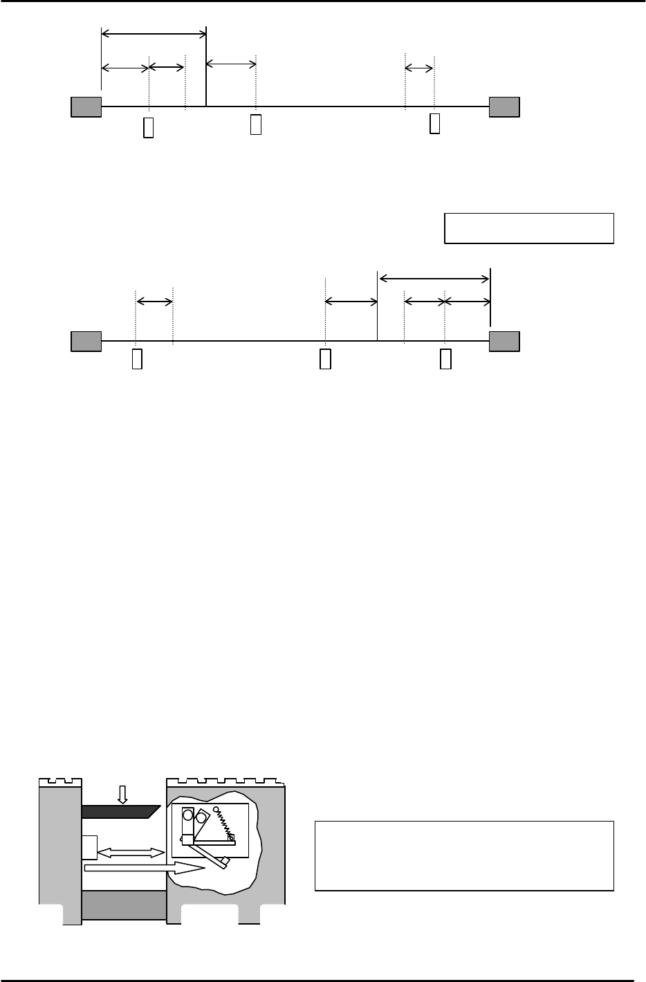
3.15 D-axis Interference Prevention Sensor Adjustment
1. Ensure that the sensor face is parallel to the D-axis ball screw.
2. Set the amplifier volume on the sensor 1 to 1.5 scales from where the beams click. (Middle of Min
and Max.)
3. Zero set the D1 and D2 tables, then move both tables to around the center of the machine.
4. Manually rotate the ball screw so D1 contacts D2. Move D1 2700 pulses (23mm) back from this
position.
5. Adjust the flag so the interference prevention sensor activates when the clearance
between both tables is 2700 pulses. (Tolerance: 2700 +/-25 pulses)
Max Limit Position
Min Limit Position
– OT
+ OT
+ Stopper
– Stopper
Zero Set Sensor
D1- axis
0 Position
2500
3750
117
1407
117
Figure 30
– OT
+ OT
+ Stopper
– Stopper
Zero Set Sensor
Min Limit Position
Max Limit Position
D2- axis
117
0 Position
117
2500
3750
1407
Figure 31
Light beam
Ball screw
2700pulses
Interference
prevention flag
Figure 32
Jog the table to check that the
servo power
is cut when this sensor activates.
(This sensor is the +OT of D1 and D2.)
Views from rear of M/C
FK-9F98-05 CP-643E Training Text for Service Engineers
Edition 5.0 Chapter 3. X, Y, Z and D-axes Adjustment [20/26]
Fuji Machine Mfg. Co., Ltd. Okazaki
SMT Equipment Quality Assurance Dept.
Technical Support Div. Section No.2
3-20
6. To set the travel limits (Min Limit D1) and (Max Limit D2) follow the procedure below:
a. Zero set both device tables.
b. Manually move D1 toward D2 (D2 is at 0 pulses) until the interference prevention sensor
triggers. Move D1 back 117 pulses (Min Limit Pos. D1) and enter the pulse count at the host
PC.
c. Position D1 to 0 pulses, move D2 toward D1 until the interference prevention sensor triggers.
Move D2 back 117 pulses (Max Limit Pos. D2) and enter the pulse count at the host PC.
D1-axis Servo Counter Table 0.00853mm/pulse Standard Value
Plus Mechanical Stopper
3750 ± 100
Minus OT Sensor ON
2343 ± 100
Max Limit Pos. D1
2226 ± 100
D1 ORIGINAL 0
Zero Set Sensor ON
- 2500 ± 100
PICKUP POS. T1
- 266648 ± 200
Min Limit Pos. D1 Plus OT +117
Plus OT Sensor ON Less than - 267457
IMPORTANT
Be aware that the (+) and (-) signs appear opposite between mechanical check mode and
normal operation for the D1-axis counter.
The tables here represent the pulse count values using normal operation mode.
D2 Servo Counter Table 0.00853mm/Pulse Standard Value
Minus Mechanical Stopper - 3750 ± 100
Minus OT Sensor ON - 2343 ± 100
Min Limit Pos. D2 - 2226 ± 100
D2 ORIGINAL 0
Zero Set Sensor ON 2500 ± 100
PICKUP POS. T2 137883 ± 200
Max Limit Pos. D2 Plus OT - 117
Plus OT Sensor ON More than 267657
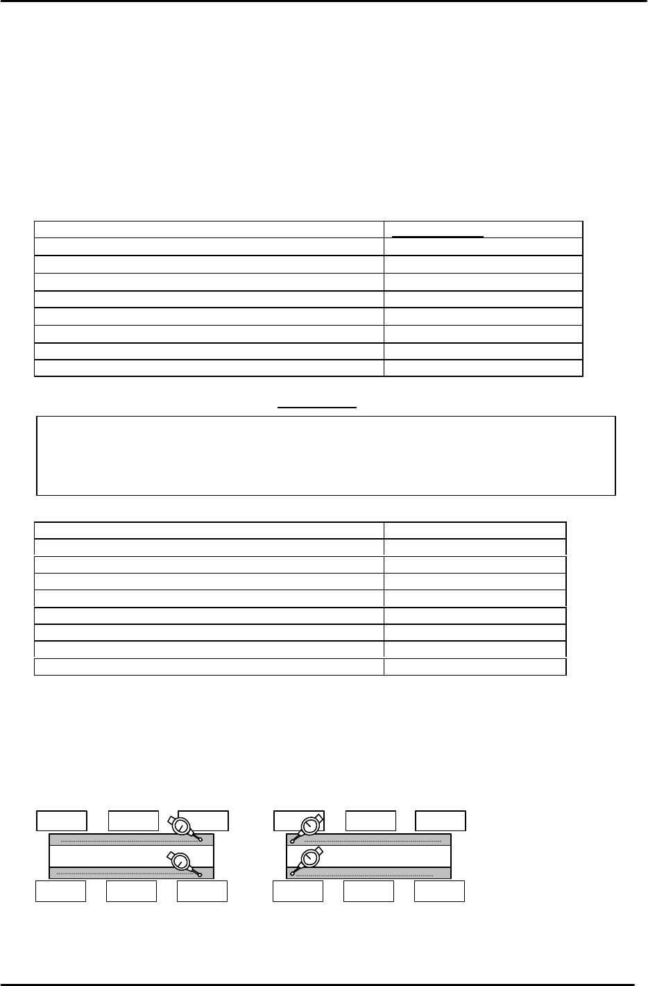
3.16 D-axis Pallet Flatness Measurement
1. Flatness of the top plates on the pallets is important to maintain consistent pick up. Set up two dial
gauges as pictured and indicate the top surface of the feeder plate at the positions illustrated in
Fig.34. (Tolerance: within 0.1mm)
2. If the flatness measurement is out of tolerance, contact Fuji for further instructions.
0
D2Pallet
0
D1Pallet
0
Figure 33
FK-9F98-05 CP-643E Training Text for Service Engineers
Edition 5.0 Chapter 3. X, Y, Z and D-axes Adjustment [21/26]
Fuji Machine Mfg. Co., Ltd. Okazaki
SMT Equipment Quality Assurance Dept.
Technical Support Div. Section No.2
3-21
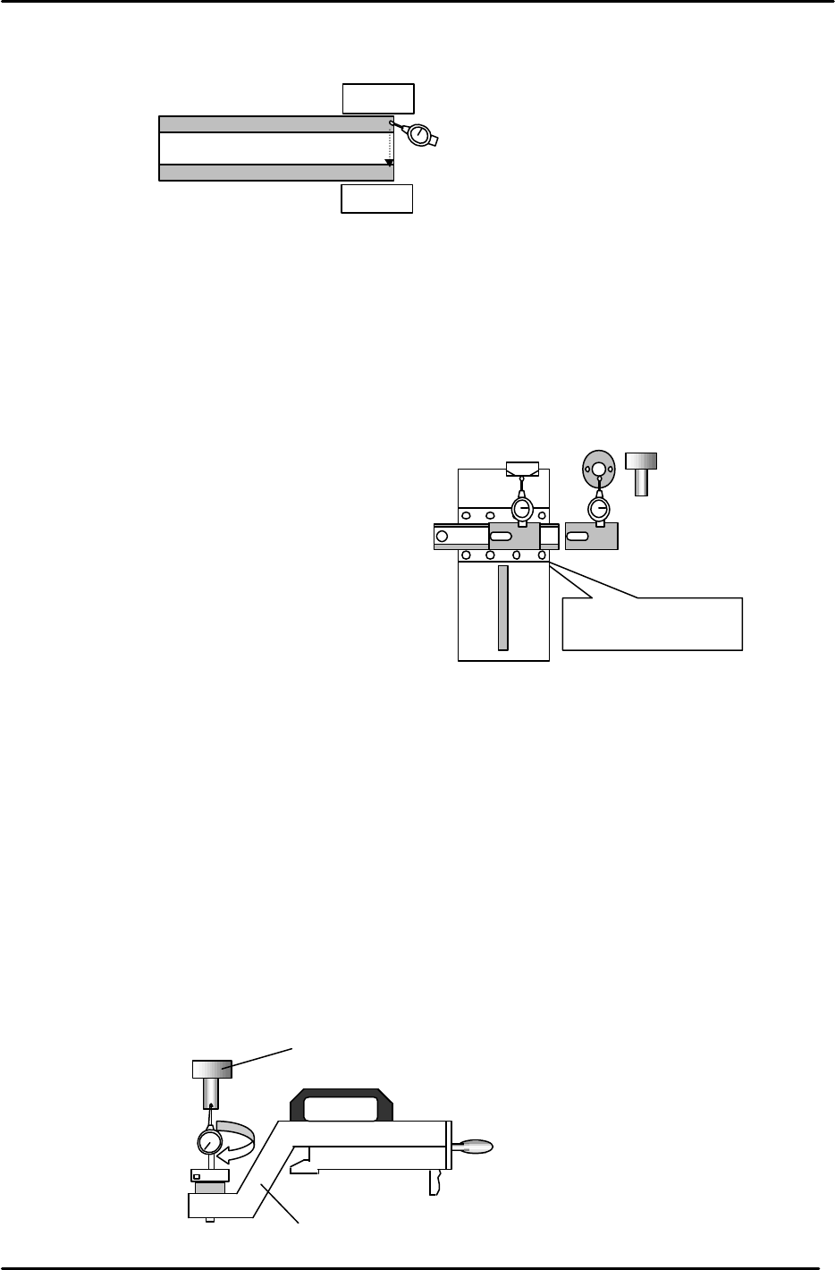
3. Set a dial gauge and block on the machine base and check the flatness from A to B.
(Tolerance: within 0.05mm)
3.17 Cam Box Positioning Check
1. Attach the positioning jig onto the A Shaft and turn the Pick-up valve ON.
2. Position the A shaft at station 1 and set the cam to 200 degrees.
3. Install the cam box alignment jig on the D1 table.
(Tolerance: 0 to + 0.05mm)
4. Check the cam box position at slots 3 & 68 of D1 & D2
3.18 Pick up Position Calibration
1. Attach the positioning jig onto the A Shaft. (Jig No.:ADCPJ8130)
2. Set the “Pick up Position” jig on the D1/D2 table at slot No.1. (Jig No.:Z9913AWPJ9330)
3. Turn the Pick-up valve ON and set the cam to 170 degrees at Station 1.
4. Balance the dial gauge on both sides of the positioning jig in the X-direction.
When the gauge is balanced on each side, this becomes pick up position D1/D2.
5. When balanced, enter the pulse count into the proper at the host PC.
0
D1 Pallet
A
Dial Gauge Block
Jig No.: Z5313WPJ0070
Figure 34
Do not inch
with
the
jig
attached to the table.
0 to 0.05mm
Cam box alignment
Jig No.: ADCPJ8270
JIG A
(Jig No.: 71615WPJ2070)
Figure 35
Figure 36
“
Pick up
pos
”
jig
(Jig No.: Z9913AWPJ89330)
(Jig No.: 71615WPJ2070)