CP643E.pdf - 第46页
FK-9F98-05 CP- 643E Training Text for Service Engineers Edition 5.0 Chapter 4. Station Adjustment [ 1 /18] Fuji Machine Mfg. Co., Ltd. Okazaki SMT Equipment Quality Assurance Dept. Technical Support Div. Section No.2 4- …
FK-9F98-05 CP-643E Training Text for Service Engineers
Edition 5.0 Chapter 3. X, Y, Z and D-axes Adjustment [26/26]
Fuji Machine Mfg. Co., Ltd. Okazaki
SMT Equipment Quality Assurance Dept.
Technical Support Div. Section No.2
3-26
3.24 Upward and Downward End Sensor Adjustment (Stations 1 & 11)
1. Set the cam angle to 0 degrees. Turn the Pick-up (Y020) and Placing valves ON. (Y028)
2. Set a dial indicator at the tip of the cam lever (fig. 46) Turn the cam until the dial gauge deflects 0.30
to 0.40. Adjust the sensor bracket so the sensor turns OFF between 0.30 to 0.40. (fig. 48)
3. Set the cam angle to 200 degrees to adjust the downward end sensor. The downward end sensor is
ON when the lever ascends 0.30 to 0.40mm. Adjust the sensor bracket to turn OFF this sensor.
(fig.49)
4. Adjust the upward end sensor for the 1st in the same manner. (It is not possible to adjust if the flag
is installed at an angle.
5. Confirm sensor reaction in I/O.
<I/O à Standard I/O à IN>
X03F ST11 DN POS
X06A ST1 UP POS
X06B ST11 UP POS
Note: for further details on this adjustment, refer to the CP-6 Series Reference Manual.
Place the dial gauge here
Figure 46
Down end sensor
Up end sensor
Station 11
Station 1
Nozzle index unit
Up end sensor
Figure 47
The down end sensor should turn
OFF when the lever lifts 0.3 to
0.4mm from 200 degrees.
Figure 49
Sensor flag
Down end sensor
The up end sensor should turn
OFF when the lever lowers 0.3 to
0.4mm from 0 degrees.
Figure 48
FK-9F98-05 CP-643E Training Text for Service Engineers
Edition 5.0 Chapter 4. Station Adjustment [1/18]
Fuji Machine Mfg. Co., Ltd. Okazaki
SMT Equipment Quality Assurance Dept.
Technical Support Div. Section No.2
4-
1
Chapter 4 Station Adjustment
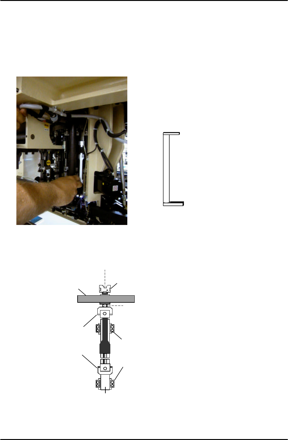
4.1 Shaft Assembly Adjustment
1. Rotate shaft A to the 19
th
station.
2. Make sure that there is a nozzle holder on shaft A.
3. Check the alignment of the holder and clutch. Use the jig indicated in Fig.1.
4. If the holder and clutch are not aligned correctly, use a 10mm spanner at position A in fig. 2; and
a 3.0mm L-wrench at position B, to loosen the shaft assembly and realign them.
5. When the clutch and holder on the shaft assembly are correctly aligned, there should be no
resistance with the jig.
6. Finally, in preparation for the adjustments that follow, remove the holder from shaft A.
Coupling
Nut retainer
A
Helical gear
Clutch
Linear guide rail
B
Figure 2
19
TH
station alignment Jig No. WPJ0102
Figure 1
FK-9F98-05 CP-643E Training Text for Service Engineers
Edition 5.0 Chapter 4. Station Adjustment [2/18]
Fuji Machine Mfg. Co., Ltd. Okazaki
SMT Equipment Quality Assurance Dept.
Technical Support Div. Section No.2
4-
2
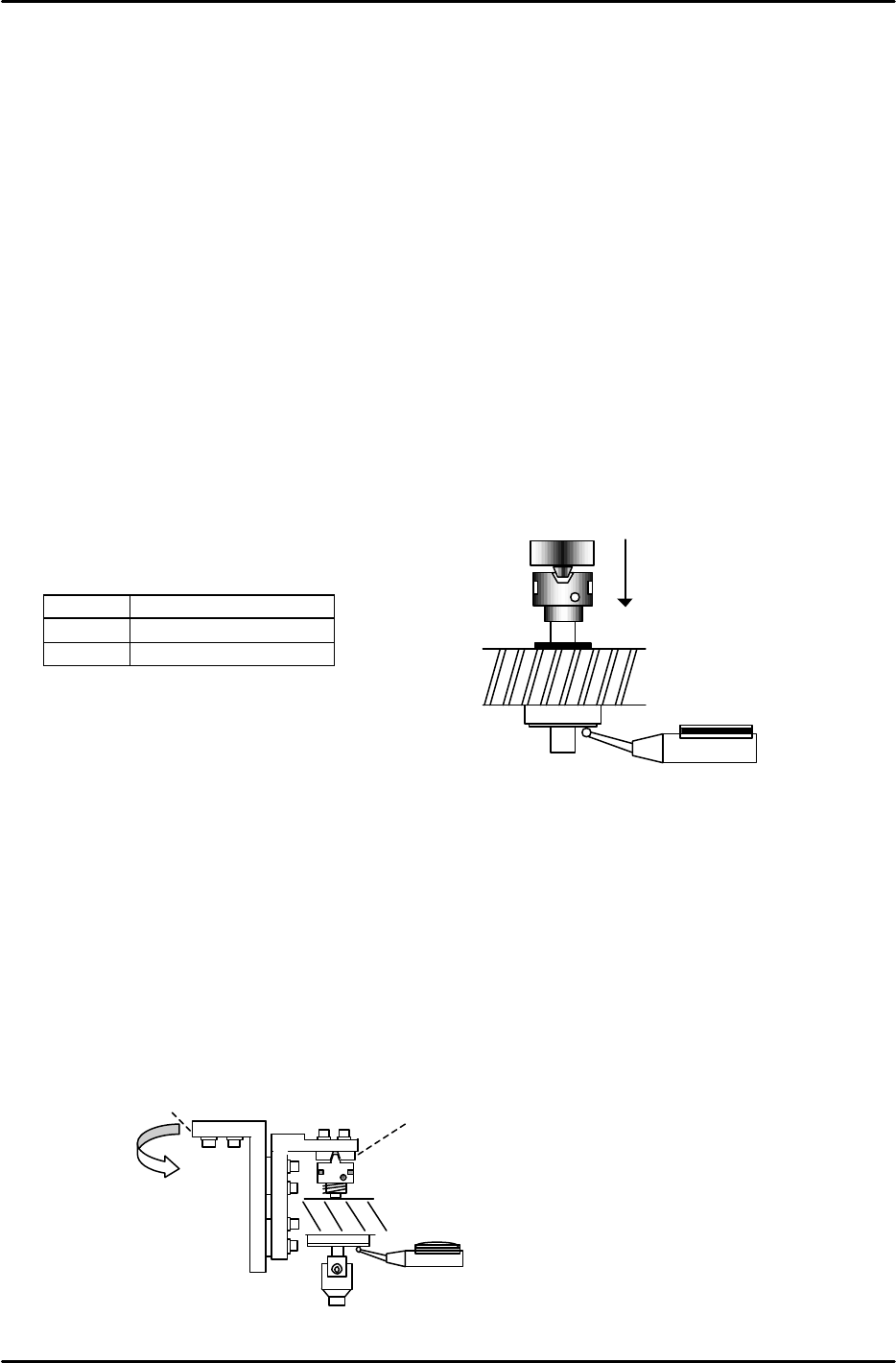
4.2 Stroke Adjustment
Adjust the clutch stroke of stations; 3,10,12 and 13 as described below.
1. Remove the sensor bracket at station 12 and put it aside.
2. Measure and record the deflection of each shaft clutch at 200 degrees. (rotate the shaft to find
the absolute low point.) When the clutch is at the downward end position and manually rotated,
the dial indicator should read within 0.01 to 0.02mm.
3. After measuring all the shafts, find the shaft with the least deflection amount and record it as the
“LOW” shaft.
4. Using the LOW shaft, set the stroke at stations 3,10,12, and 13.
Turn the solenoid valve ON only for the station being adjusted at the time. Otherwise, all valves
should be OFF. ( No valve used at the 12
th
station)
5. When the rotor engages with the nozzle clutch at 200 degrees, adjust the rod so that the nozzle
clutch is pressed downward on the LOW shaft 0.30 to 0.35mm. (0.31 is the ideal value)
<I/O à Standard I/O à OUT>
Y030 FQ SOL
Y022 PQ ROT SOL ON
Y02C PRQ ROT SOL ON
4.3 Station 5 Origin Position and Stroke Adjustment
1. This adjustment should be performed with the servo power OFF.
2. Move the LOW shaft to station 5 and set at 200 degrees.
3. Engage and align the 5th station clutch (1) with the reference shaft, by adjusting the position of
bracket (2):
1
2
Figure 4
Scale --- 0.3mm
Figure 3