CP643E.pdf - 第73页
FK-9F98-05 CP- 643E Training Text for Service Engineers Edition 5.0 Chapter 5. Loader and Conveyor Adjustment [ 10 / 28 ] Fuji Machine Mfg. Co., Ltd. Okazaki SMT Equipment Quality Assurance Dept. Technical Support Div. S…
FK-9F98-05 CP-643E Training Text for Service Engineers
Edition 5.0 Chapter 5. Loader and Conveyor Adjustment [9/28]
Fuji Machine Mfg. Co., Ltd. Okazaki
SMT Equipment Quality Assurance Dept.
Technical Support Div. Section No.2
5-
9
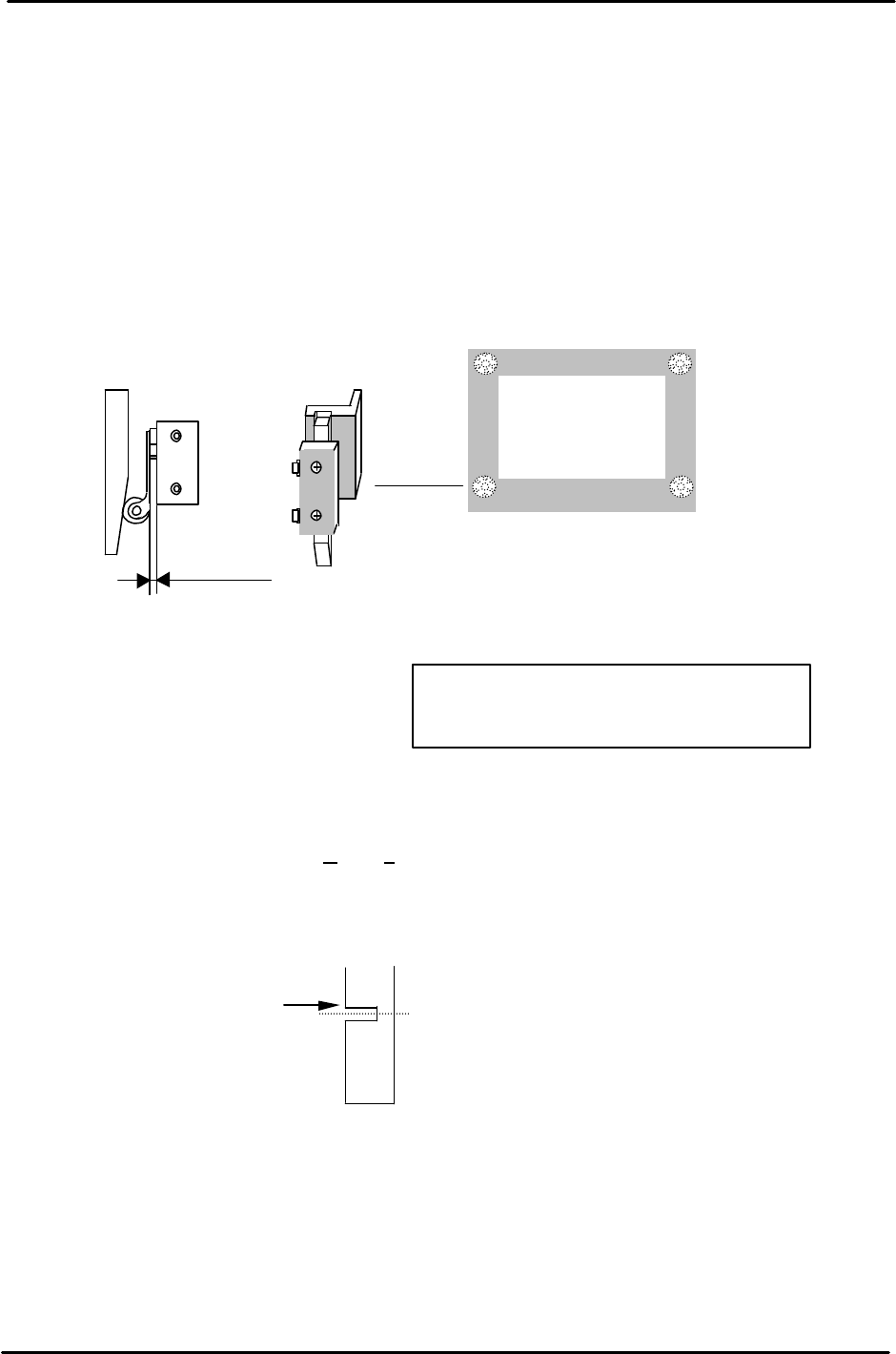
5.12 Z-axis Mechanical Valve Adjustment
1. Adjust the mechanical valve and dog for the moveable rail locking cylinders as follows.
The moveable rail on the main table should lock when the Z-axis is positioned at;
[ZL lower – 650 +/- 50 pulses.]
2. If out of range, move the dog up or down until the rail clamps within the specified range.
3. After adjustment, make sure the pneumatic swich lever has 1 to 2mm of play. Too much pressure
on the lever will result in damage to the pneumatic switch.
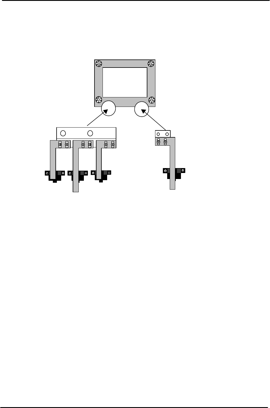
5.13 Z-axis Sensor Adjustment
1. Set the Upper End Sensor 2 flag (Fig. 17) at [ Z0 + 2300 ± 50pls.]
(Standard I/O: X065 M-LFTR UP2)
2. Set the Upper End Sensor 1 (Middle Load Position) flag (Fig. 17) at
[ ZL (Lower) – 10500 – 125 ± 50pls.]
(Standard I/O: X064 M-LFTR UP1)
3. Calculate the Middle Loading Position (Proper Data) as follows:
CP-643E [ML= ZL Lower – 10500 ± 50pls.]
Note: this is a proper data item for the Middle Load Pos., once calculated, enter it into proper at
the host PC.
4. Set the Downward End Sensor flag (Fig. 18) at [Z0 + 400 ± 50pls.]
(Standard I/O: X067 M-LFTR DWN END)
1
to
2mm
play
Figure 16
Move the flag to trigger
the sensor at this edge.
Middle Load Position
Figure 17
Remove the MOT flag to allow adjustment
for all other sensors first. Adjust the MOT
last.
FK-9F98-05 CP-643E Training Text for Service Engineers
Edition 5.0 Chapter 5. Loader and Conveyor Adjustment [10/28]
Fuji Machine Mfg. Co., Ltd. Okazaki
SMT Equipment Quality Assurance Dept.
Technical Support Div. Section No.2
5-
10
5. Set the MOT sensor flag (Fig. 17) at [ Z0 +150 ± 50pls.]
(Standard I/O: X066 M-LFTR )
6. Ensure the flags are centered within the sensors after adjustment.
Upward end sensor 2
Upward end sensor 1
Downward end sensor
MOT Sensor
Figure 18
FK-9F98-05 CP-643E Training Text for Service Engineers
Edition 5.0 Chapter 5. Loader and Conveyor Adjustment [11/28]
Fuji Machine Mfg. Co., Ltd. Okazaki
SMT Equipment Quality Assurance Dept.
Technical Support Div. Section No.2
5-
11
5.14 Loading Position Check Sensor
1. For both the IN and OUT loading positions, adjust the bracket so that the light beam from the
sensor is centered on the silver area of the dog when the XY-table is at each loading position.
2. Set the clearance between the sensor and the dog to 11.5mm. The sensor shall be ON only at the
silver area. If not, adjust the amplifier sensitivity or sensor positioning.
<<Instructions for adjusting the Loading Position Check Sensor>>
“OMRON E3X-NH11”
1. Set to “L_ON”.
2. Set to “ADJ”. Adjust ? , ? or “SET” button so that the red lamp
comes to the center position.
3. Set to “TEACH”. Position the sensor beam over the silver area
on the sticker. Press “SET” once.
4. Position the sensor beam over the black area on the sticker. Press
“SET” once.
5. Set to “RUN”.
<<CHECK>>
1. The red lamps change in volume between ON and OFF conditions.
2. All green lamps will light when the sensor beam light is
positioned over the silver area.
3. One green lamp will light when the sensor beam light is
positioned over the black area.
4. Confirm sensor reaction by I/O.
<I/O à Standard I/O à IN>
X068 XY IN L POS
X069 XY OUT L POS
11.5mm
CE
ADJ
OUT
SET
TEAC
H
RUN
D.
ON
L
ON
E3X- NH11
Figure 19