CP643E.pdf - 第109页
FK-9F98- 05 CP- 643E Training Text for Service Engineers Edition 5.0 Chapter 7. Camera Adjustment [ 4 / 10] Fuji Machine Mfg. Co., Ltd. Okazaki SMT Equipment Quality Assurance Dept. Technical Support Div. Section No.2 7-…
FK-9F98-05 CP-643E Training Text for Service Engineers
Edition 5.0 Chapter 7. Camera Adjustment [3/10]
Fuji Machine Mfg. Co., Ltd. Okazaki
SMT Equipment Quality Assurance Dept.
Technical Support Div. Section No.2
7-3
7.3 Camera Centering
1. Set a straight 0.7mm nozzle at station 6 and set the cam at 200 degrees.
2. View the raw image of the nozzle using the following commands:
[SET] → [MANUAL] → [VISION] → [ADJUST] → [GET ACQ] → [GET ACQ] → [CHANGE] →
(SELECT CAMERA) → [DSP REAL-IMG]
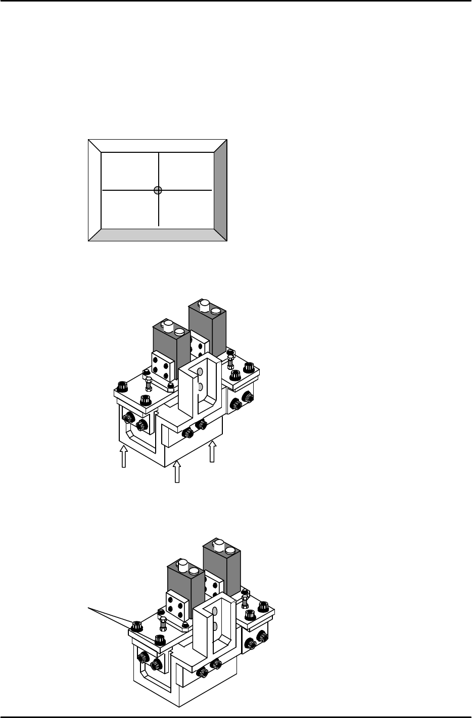
3. The nozzle image and crosshairs will appear on the screen.
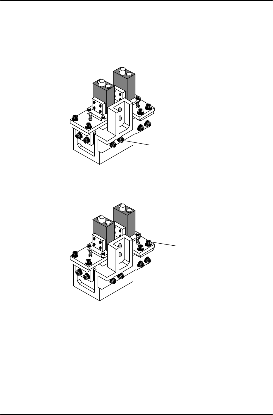
4. To align the Wide Camera nozzle image to the crosshairs in the Y-direction, loosen the three bolts
on the underside of the camera assembly and adjust the position of the assembly accordingly (see
figure 7). Once the adjustment is complete tighten the bolts with the required amount of torque
(13Nm).
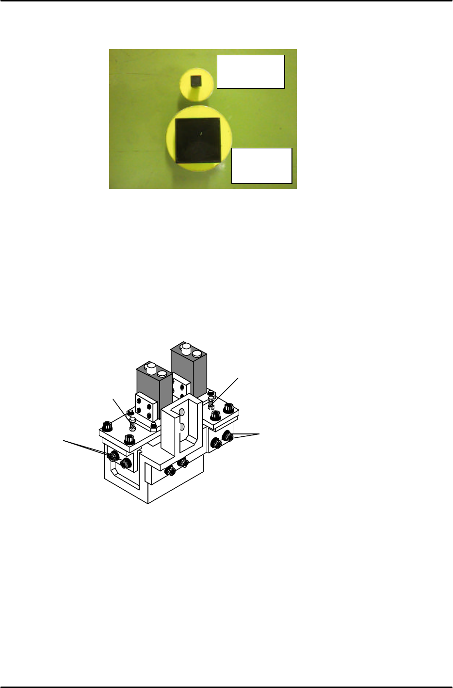
5. To align the Wide Camera nozzle image to the crosshairs in the X-direction, loosen the X-axis
positioning bolts (Item 1 in figure 8) and adjust the position of the camera accordingly. Once the
adjustment is complete tighten the bolts with the required amount of torque (8 Nm).
Figure 6
Rear View
Figure 7
Rear View
Figure 8
1
13N.m
FK-9F98-05 CP-643E Training Text for Service Engineers
Edition 5.0 Chapter 7. Camera Adjustment [4/10]
Fuji Machine Mfg. Co., Ltd. Okazaki
SMT Equipment Quality Assurance Dept.
Technical Support Div. Section No.2
7-4
6. As the narrow camera bracket is attached to the wide camera bracket, it is necessary to adjust the
wide camera bracket first when adjusting both cameras. Performing narrow camera adjustments
first will necessitate the adjustment being performed twice.
7. To adjust the narrow camera in the Y-direction, loosen the Y-axis positioning bolts (Item 1 in figure 9)
and adjust the camera position accordingly. Once the adjustment is complete, tighten the bolts with
the required amount of torque (13Nm).
8. To adjust the narrow camera in the X-direction, loosen the X-axis positioning bolts (Item 1 in figure
10) and adjust the camera position accordingly. Once the adjustment is complete tighten the bolts
with the required amount of torque (8Nm).
Rear View
Figure 9
1
Rear View
Figure 10
1
FK-9F98-05 CP-643E Training Text for Service Engineers
Edition 5.0 Chapter 7. Camera Adjustment [5/10]
Fuji Machine Mfg. Co., Ltd. Okazaki
SMT Equipment Quality Assurance Dept.
Technical Support Div. Section No.2
7-5
7.4 Focus Adjustments
1. Before proceeding to set the focus, ensure the cameras (nozzle images) are centered.
2. Place the wide camera inspection jig on head A and bring it to the 6
th
station at 200 degrees.
3. Display the wide camera monitor using the following commands:
[SET] → [MANUAL] → [VISION] → [ADJUST] → [GET ACQ] → [GET ACQ] → [CHANGE] →
(SELECT CAMERA) → [DISPLAY]
4. Adjust the focus of the wide camera by loosening the two positioning bolts (1) and use the focus
adjustment bolt (2) to raise or lower the camera (see figure 12).
5. The camera is focused when the wide camera monitor shows a clear, sharp image of the wide
camera inspection jig.
6. Once the adjustment is complete, tighten the bolts with the required amount of torque (13Nm).
7. Adjust the focus of the narrow camera by loosening the two positioning bolts (3) and use the focus
adjustment bolt (4) to raise or lower the camera (see figure 12).
8. When both adjustments are finished set the gap between the lens cover and the prism box to 0.5mm.
Narrow camera
inspection jig
Wide camera
inspection jig
Figure 11
Rear View
Figure 12
1
2
3
4