CP643E.pdf - 第118页
FK-9F98- 05 CP-643E Training Text for Service Engineers Edition 5.0 Chapter 8. Placement [ 3 / 6] Fuji Machine Mfg. Co., Ltd. Okazaki SMT Equipment Quality Assuranc e Dept. Technical Support Div. Section No.2 8 - 3 13. I…

FK-9F98-05 CP-643E Training Text for Service Engineers
Edition 5.0 Chapter 8. Placement [2/6]
Fuji Machine Mfg. Co., Ltd. Okazaki
SMT Equipment Quality Assurance Dept.
Technical Support Div. Section No.2
8
-
2
M/C PAM Procedure
1. Prepare the Nozzle Assignment Table in the PGO so 1.30Ø nozzles are installed at holder position
3 and 0.70Ø nozzles are installed in position 1. (Actually, the configuration does not matter other
than to make sure the nozzle # 1 is included in the center test data.) The # 1 nozzle is used as the
reference for all other nozzle locations. (It is important for the # 1 nozzle to be measured.)
2. Set the bend limit for holders 1 and 3 to 0.05mm.
3. Carry out nozzle center measurement. Select: [SET] → [MANUAL] → [CENTER] and press Start.
Make sure nozzle # 1 is measured during centering as it is the reference for all other nozzles.
If any nozzles fail the center test, change the bad nozzle(s) and run center until all nozzles pass.
4. Receive the proper data to the host computer.
5. Edit the X / Y placing offset Proper data (at the host) so all values equal 0.
6. Replace the system Rom card with the PAM Rom card, then boot by Reset Start.
7. Transmit the proper, status and programs to the machine. After transmitting the data, turn the
power OFF and reboot.
8. Load the PAM board using the loader commands on the main menu. Clamp the PAM board using
two tooling pins. Ensure the board is properly seated on the pins.
9. Load the PAM components at slot # 1 on D1.
10. First, select the Narrow PAM program and press: [PAM] → [PLACE] → [START]
11. After placement is finished, leave the board on the XY table, select [MEASURE] and press Start.
12. The Avg. dX/ dY results will appear on the monitor as indicated in figure 1.
Note: If the Avg. dX/ dY results are greater than 10, re-calibrate X0/Y0 and Xc/Yc.
Note: The unit of measurement is 1/100mm for dX/ dY. The data entered in the proper placing offset is
in units of 1/100. The average deviation is rounded up to the nearest 1/100 from an initial
precision of 1/1000.
CP_6.PAM.PROGRAM
Prod 00004 Sche 00000
V1.01
off line
Proper
Input Data
Data Save
Return
Page150
XY
C
jog
000000000000000
000000000000000
Proper data
HEAD Proper X Proper Y Avg. dX Avg. dY
A 0 0 -7 5
B 0 0 -8 4
C 0 0 -5 5
D 0 0 -7 4
E 0 0 -8 3
F 0 0 -6 5
G 0 0 -8 6
H 0 0 -5 7
I 0 0 -6 7
J 0 0 -7 6
Operation: Front
Ready
Nozzle Skip
1 ABCDEF 2 ABCDEF
3 ABCDEF 4 ABCDEF
5 ABCDEF 6 ABCDEF
Figure 1
FK-9F98-05 CP-643E Training Text for Service Engineers
Edition 5.0 Chapter 8. Placement [3/6]
Fuji Machine Mfg. Co., Ltd. Okazaki
SMT Equipment Quality Assurance Dept.
Technical Support Div. Section No.2
8
-
3
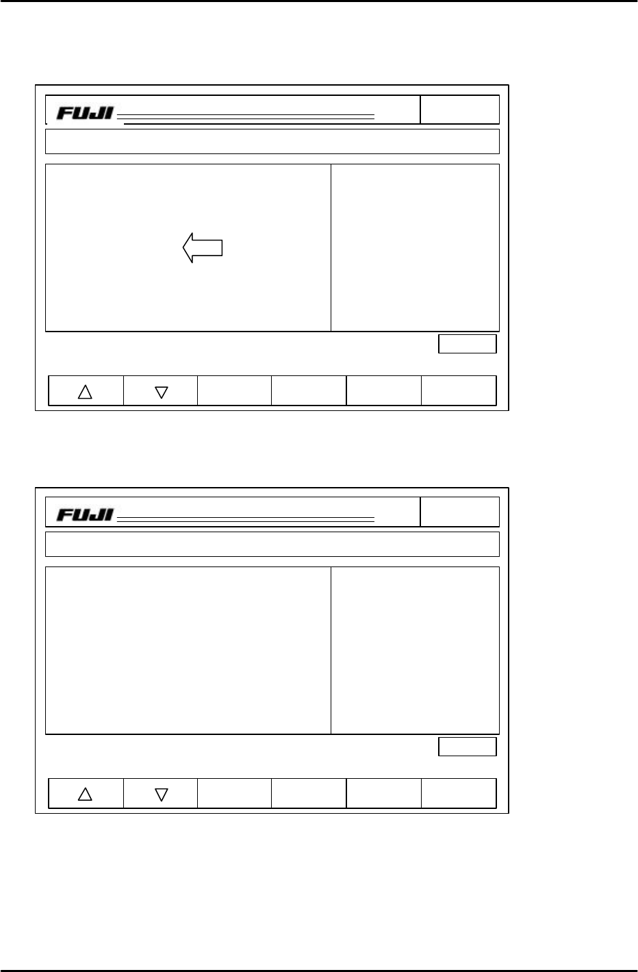
13. If the Avg. dX/dY results are less than 10, transfer the Avg. dX and Avg. dY results to Proper X and
Proper Y (see fig. 2) Press: INCHING F + INCHING 1 together and press F4 on the display twice
to transfer the Avg. dX/ dY figures to the Proper X/Y columns. (This is only done during this time)
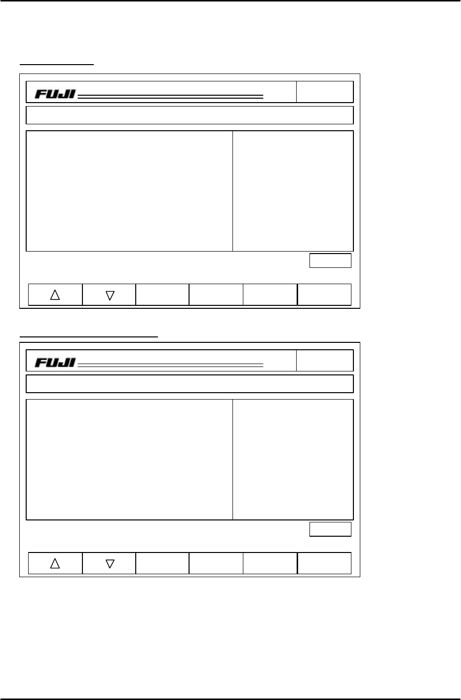
14. Run the Narrow program again and check the results. (fig.3) If the values for Avg. dX/ dY are less
than 2, the procedure is complete. If not, proceed to step 15.
CP_6.PAM.PROGRAM
Prod 00004 Sche 00000
V1.01
off line
Proper
Input Data
Data Save
Return
Page150
XY
C
jog
000000000000000
000000000000000
Proper data
HEAD Proper X Proper Y Avg. dX Avg. dY
A -7 5 -7 5
B -8 4 -8 4
C -5 5 -5 5
D -7 4 -7 4
E -8 3 -8 3
F -6 5 -6 5
G -8 6 -8 6
H -5 7 -5 7
I -6 7 -6 7
J -7 6 -7 6
Operation: Front
Ready
Nozzle Skip
1 ABCDEF 2 ABCDEF
3 ABCDEF 4 ABCDEF
5 ABCDEF 6 ABCDEF
Figure 2
Figure 3
CP_6.PAM.PROGRAM
Prod 00004 Sche 00000
V1.01
off line
Proper
Input Data
Data Save
Return
Page150
XY
C
jog
000000000000000
000000000000000
Proper data
HEAD Proper X Proper Y Avg. dX Avg. dY
A -7 5 0 0
B -8 4 -1 0
C -5 5 0 0
D -7 4 -2 1
E -8 3 0 2
F -6 5 0 1
G -8 6 -1 1
H -5 7 0 0
I -6 7 -2 1
J -7 6 -1 1
Operation: Front
Ready
Nozzle Skip
1 ABCDEF 2 ABCDEF
3 ABCDEF 4 ABCDEF
5 ABCDEF 6 ABCDEF
FK-9F98-05 CP-643E Training Text for Service Engineers
Edition 5.0 Chapter 8. Placement [4/6]
Fuji Machine Mfg. Co., Ltd. Okazaki
SMT Equipment Quality Assurance Dept.
Technical Support Div. Section No.2
8
-
4
15. If the values are greater than 2, take half of the result from dX/dY and add or subtract the value to
the current Proper X / Y data. (fig. 4) Repeat this until the Avg. dX/ dY values are 0 +/- 2.
Example results
Data after editing Proper X / Y
16. Once the Avg. dX/ dY values are less than 2, select the Wide PAM program to check that the
results are within the prescribed tolerance limits. If out of range, the cameras need to be re-
centered and calibrated. Refer to chapter 7 for details.
Note: There are only one set of placing offsets (X/Y) in the proper, if the narrow camera results are
good and the wide camera results are bad, the camera positioning is incorrect.
CP_6.PAM.PROGRAM
Prod 00004 Sche 00000
V1.01
off line
Proper
Input Data
Data Save
Return
Page150
XY
C
jog
000000000000000
000000000000000
Proper data
HEAD Proper X Proper Y Avg. dX Avg. dY
A -7 5 0 4
B -8 4 -6 4
C -5 5 0 2
D -7 4 -4 1
E -8 3 -2 2
F -6 5 0 1
G -8 6 -1 1
H -5 7 0 0
I -6 7 -6 1
J -7 6 -1 1
Operation: Front
Ready
Nozzle Skip
1 ABCDEF 2 ABCDEF
3 ABCDEF 4 ABCDEF
5 ABCDEF 6 ABCDEF
CP_6.PAM.PROGRAM
Prod 00004 Sche 00000
V1.01
off line
Proper
Input Data
Data Save
Return
Page150
XY
C
jog
000000000000000
000000000000000
Proper data
HEAD Proper X Proper Y Avg. dX Avg. dY
A -7 7 0 4
B -11 6 -6 4
C -5 6 0 2
D -9 5 -4 1
E -9 4 -2 2
F -6 6 0 1
G -9 7 -1 1
H -5 7 0 0
I -9 8 -6 1
J -8 7 -1 1
Operation: Front
Ready
Nozzle Skip
1 ABCDEF 2 ABCDEF
3 ABCDEF 4 ABCDEF
5 ABCDEF 6 ABCDEF
Figure 4
Figure 5